|
|
|
Categories
|
|
Information
|
|
Featured Product
|
|
|
 |
|
|
There are currently no product reviews.
 ;
Good morning, the service manual you sent me was perfect.
Your service and answering are excellent.
I recomend this service.
Best regards.
 ;
I had been looking everywhere for a proper service manual for this VCR. Everywhere else that has this available for download has a very light version. This is the full service manual with all aspects that would interest anyone looking for the service manual for the AIWA HV-MX100 Worldwide VHS VCR. Great quality (as always). A winner hands down. Best Quality.
;
Top quality manual. Covers all aspects you'd expect in a top quality service manual for this Panasonic VHS VCR. The manual resolution is high. Another top quality manual from the only site worth downloading manuals from! If you're looking for a manual for the PV-9662 VHS VCR, this is the one you'll want to get!
;
complete part-lists and pcb layout, schematic diagram is good enlargable,
;
Excellent, fast delivery, excellent product. Good luck!
3.2.4 ASSEMBLY/DISASSEMBLY OF [9] OP BLOCK ASSMBLY/CCD BOARD ASSEMBLY CAUTIONS (1) During the procedure, be careful in handling the CCD IMAGE SENSOR, the OP LPF, and the LENS etc., especially not to damage or soil their surface. If it is soiled with fingerprints, etc., gently clean it with chamois or the cleaning cloth. (2) When the unit is shipped from the factory, a protection seal is sometimes applied onto the transparent glass of the CCD IMAGE SENSOR. Leave the protection seal as it is, and take it off just before assembling the CCD IMAGE SENSOR to the OP BLOCK ASSEMBLY. Disassembly procedure of OP BLOCK ASSEMBLY/CCD BOARD ASSEMBLY (1) Unsolder the 14 soldered points (SD9), and remove the CCD BOARD ASSEMBLY. (2) Remove the 2 screws (1 and 2), and remove the CCD BASE ASSEMBLY. NOTE 9a: When removing the CCD BASE ASSEMBLY, be careful not to lose or damage the SPACER or the OP LPF because they may be removed together with the CCD IMAGE SENSOR. NOTE 9b: In replacing the CCD IMAGE SENSOR, don't remove the CCD IMAGE SENSOR from the CCD BASE ASSEMBLY. Instead, replace the whole CCD BASE ASSEMBLY. Assembly procedure of OP BLOCK ASSEMBLY/CCD BOARD ASSEMBLY (1) Attach the OP LPF, the SHEET, and the SPACER to the OP BLOCK ASSEMBLY in this order. (2) Attach the CCD BASE ASSEMBLY so that the spacer is not shifted, and tighten the CCD BASE ASSEMBLY with the 2 screws (1 and 2). (3) Insert the CCD BOARD ASSEMBLY to the CCD BASE ASSEMBLY, and solder the 14 points (SD2). Replacement of service repair parts Service repair parts of the OP BLOCK ASSEMBLY are as follows. When replacing the parts, be careful not to cut or damage the FPC, and not to damage the parts due to soldering (overheat). (1) Focus motor (2) Zoom motor (3) Iris motor unit NOTE 9c: To solder the FPC, lift the FPC approx.1mm away from the jack when replacing the FOCUS MOTOR or the ZOOM MOTOR. NOTE 9d: The IRIS MOTOR UNIT contains the FPC ASSEMBLY and the SENSOR �2.
1 (S9a) 7 (S9c) 8 (S9c) 9 11 (S9b) (S9b)
CCD BOARD ASSEMBLY IRIS MOTOR UNIT <NOTE 9c, d>
10 (S9b)
OP side
OP LPF SD9
Blue CCD side
2 (S9a)
6 5 (S9b) (S9b) FOCUS MOTOR <NOTE 9c> <NOTE 9a, b> CCD BASE ASSEMBLY SPACER
SHEET
SENSOR
4 (S9b)
OP LPF
3 (S9b)
0.078N.m (0.8kgf.cm) 0.118N.m (1.2kgf.cm)
OP BLOCK
ZOOM MOTOR <NOTE 9c>
Fig.3-2-4
1-14 (No.YF005)
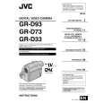 $4.99 GR-D73US JVC
Owner's Manual Complete owner's manual in digital format. The manual will be available for download as PDF file aft…
|
|
|
> |
|