|
|
|
Categories
|
|
Information
|
|
Featured Product
|
|
|
 |
|
|
There are currently no product reviews.
 ;
Up to now you are the BEST! Prompt-efficient and so reasonable ! I have been after SONY service manual for quite some time !Thank you very much ! I can recomend your service to
all my collegagues ! V.Bergfield .
;
This is a very good quality print (scan) of the original SONY service manual. The original from Sony is on very thin paper. Nevertheless it is very clear and sharp and excellent readable. I'm very satisfied to have now this rare document. I've looking for it many years (infrequent). It contains very detailed circuit diagrams, exploded views, part lists, PCB view with good readable connection lines. Very recommended.
;
A complete manual with all the needed details of calibrations and service instructions about the radio receiver.
A big deal.
Many thanks !
;
Fast delivery and good quality copy. To be recommended
;
Excellent product, very clear print. Detailed circuit and assembly diagrams - this enabled me to repair my CD player with confidence. I highly recommend this site.
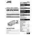
2.5 CHECKUP AND ADJUSTMENT OF MECHANISM PHASE
24 MODE GEAR
Align the MODE GEAR with the Main Deck Assembly hole. Note: The MODE GEAR may be displaced during the mechanism operation, however it can be checked from the rear and realigned during manual assembly.
27 ROTARY ENCODER
Mount the ROTARY ENCODER by aligning its mark ( and the mark ( ) of the Main Deck Assembly. Note: Be careful when handling the FPC during mounting. )
34 REEL GEAR 1
Align the REEL GEAR 1 with the Main Deck Assembly hole. Note: The REEL GEAR 1 may be displaced during mechanism operation, however this can be checked from the rear and realigned during manual assembly.
29 MAIN CAM ASSY/ 30 SLIDE ARM ASSY
When mounting the SLIDE ARM ASSY align it with the Main Deck Assembly and MAIN CAM ASSY holes. Note: During the mounting procedure, make sure that the 32 . SUB CAM ASSY is in the correct mounting position.
32 SUB CAM ASSY/ 33 CONTROL ARM ASSY
Mount the SUB CAM ASSY hole to align with the CONTROL ARM ASSY and Main Deck Assembly holes and then tighten them all together with a screw. The screw tightening torque should be 0.039 N�m (0.4 kgf�cm) Note: When mounting it, make sure that the 29 MAIN CAM ASSY is in the correct mounting position.
Fig. 2-5-1
2-14
 $4.99 GRDV3000 JVC
Owner's Manual Complete owner's manual in digital format. The manual will be available for download as PDF file aft…
|
|
|
> |
|