|
|
|
Categories
|
|
Information
|
|
Featured Product
|
|
|
 |
|
|
There are currently no product reviews.
 ;
this Manual very important when i buy this Manual i already fix the trouble of my Camera..... thanks keep up the good work.!
 ;
This service manual helped me to repair my PIONEER. Iam very satisfied, that I found it here.
Even the price of manual was not so high that person would not be able to spend a few money.
But that is very worth spent money. Thanks
;
Excellent quality service manual. Quick processing, fair prices. Love to do business again. Thank you!!!
;
Excellent service manual, the only known point of note is the alignment of improvability scanned pages within the pdf page. The resolution is good.
;
I was very glad recieving the service manal from You. Additionaly very fast. Extremaly nice servicing. Thanks very mach! Now my GX-220 working better, than it was made. Alexander from Moscow, Russia/
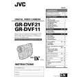
2.2.7 Checkup and adjustment of mechanism phase
<Rotary encoder> Set the �s� of the rotary part at the tapped hole as shown in the figure.
<Connect gear> (Note 2) Set the connect gear so that its locating hole meets the hole on the main deck assembly.
<Worm wheel> (Note 2) Set the worm wheel so that its locating hole meets the hole on the main deck assembly.
Note 1
<Main cam gear /Brake control plate> After fitting the main cam\ gear and brake control plat together,set them together so that their locating holes meet the hole on the main \ deck assembly.
<Connect gear 2> (Note 2) Set the connect gear 2 so that its locating hole meets the hole on the main deck assembly.
<Sub cam gear> Set the sub cam gear so that its locating hole meets the hole on the main deck assembly. This state represents that the mechanism is in the EJECT mode, which is the �mechanism assembly mode�.
Note 1: Since the connect gear 2 is tightly fixed to the main deck by caulking, adjust its phase with the connect gear and sub cam gear.
Note 2: The part that needs phase adjustment by the hole on the main deck assembly must exactly be set as the specified phase. There is a fear that some part is installed in a wrong phase because assembling of the mechanism is automated. If so, set every part in the correct phase whenever the mechanism is reassembled.
Fig. 2-2-13
2-14
|
|
|
> |
|