|
|
|
Categories
|
|
Information
|
|
Featured Product
|
|
|
 |
|
|
There are currently no product reviews.
 ;
Manual found fast and good quality, very helpfull service
;
8-17-12 Been using the sight for about 6 months. Fast Downloads and top quality
Manuels !
 ;
Everything was great, the manual, the response time, the simplicity of the order, and the
Price. The only thing that I could possible say on a negative note would be that the manual I ordered was more for a service tech. There were a lot of schematic diagrams that didn't help me solve the problem. However I would order again and recommend the web sight to others.
;
I'd been looking for this manual for awhile. Exactly what I needed - and at an excellant price. Thanks!
;
very complete. acceptable resolution. details are a little unclear. is a manual note 8.
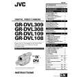
2.2.7 Checkup and adjustment of mechanism phase
<Rotary encoder> Set the �s� of the rotary part at the tapped hole as shown in the figure.
<Connect gear> (Note 2) Set the connect gear so that its locating hole meets the hole on the main deck assembly.
<Worm wheel> (Note 2) Set the worm wheel so that its locating hole meets the hole on the main deck assembly.
Note 1 <Main cam gear /Brake control plate> After fitting the main cam\ gear and brake control plat together,set them together so that their locating holes meet the hole on the main \ deck assembly.
<Connect gear 2> (Note 2) Set the connect gear 2 so that its locating hole meets the hole on the main deck assembly.
<Sub cam gear> Set the sub cam gear so that its locating hole meets the hole on the main deck assembly. This state represents that the mechanism is in the EJECT mode, which is the �mechanism assembly mode�.
Note 1: Since the connect gear 2 is tightly fixed to the main deck by caulking, adjust its phase with the connect gear and sub cam gear.
Note 2: The part that needs phase adjustment by the hole on the main deck assembly must exactly be set as the specified phase. There is a fear that some part is installed in a wrong phase because assembling of the mechanism is automated. If so, set every part in the correct phase whenever the mechanism is reassembled.
Fig. 2-2-24
2-14
|
|
|
> |
|