|
|
|
Categories
|
|
Information
|
|
Featured Product
|
|
|
 |
|
|
There are currently no product reviews.
 ;
Excellent printing quality.
A complete and very usefull service manual with all details.
GREAT SERVICE AT VERY LOW PRICE!
A+++++++++++++++++++++++++
;
Excellent printing quality.
A complete and very usefull service manual with all details.
GREAT SERVICE AT VERY LOW PRICE!
A+++++++++++++++++++++++++
;
Pioneer CDXP23S is an old model and has been top useful for me to find this Manual. CD Player is still repaired.
;
Inventory (Stock): a rather extensive list of service manuals, which are hard to find, especially 15+ yrs old.
Pricing: very reasonable.
Delivery/Response: Very Prompt delivery of product: Placed order and received download access within 1.5hrs.
Service Manual: a rather complete OEM service manual (15.5MB pdf file size). Scan quality was very good, accept for a few circuit board diagrams that were dark; Zooming, however, clarified the image. Has the required information for servicing the LD Player.
;
Perfect copy of a necessary document and my Sonic Modulator is repaired!
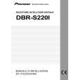
Note: The shape of the monitor assembly varies by the size of the LCD screen. For the 3.5�-type LCD, refer to Fig. 1-4-2. 1.4.3 Disassembly/assembly of monitor assembly (for 3.5�-type LCD) Note: Be careful not to soil or scratch the monitor screen through the disassembly/assembly work. 1. Remove the four screws (1 to 4) in numerical order. While disengaging the six hooks (L4a to L4f) in alphabetical order, remove the monitor cover assembly. Note4f: When removing the monitor cover assembly, be
3. Unplug the wires and FPCs from the two connectors ( c , d ), and then remove the LCD BL board assembly, holder (PWB) and backlight in that order. 4. Remove the LCD module while disengaging it from the four hooks (L4g, L4h, L4j, L4k,). 1.4.4 Disassembly/assembly of hinge assembly (for 3.5�-type LCD) 1. Remove the three screws (5 to 7), and then remove the hinge covers (1) and (2) by disengaging a total of four hooks (L4m, L4n) at the two sides. 2. Separate the SW board assembly and the FPC from the hinge assembly. Note4j: When disassembling/assembling the hinge assembly, pay careful attention to every part not to damage anything. Note4k: When connecting the FPC, arrange the FPC wire by winding it around the shaft (hinge pin) of the hinge assembly by two and a half turns while paying heed to the orientation of the hinge assembly and FPC.
(L 4 c) (L 4 f) (L 4 e)
careful not to damage the FPC and connector.
2. Unlock the connector b and then disconnect the FPC while lifting the hinge assembly upwards to remove it together with the FPC. Note4g: For disconnecting the FPC, unlock the connector first and then lift the hinge assembly upwards. Accordingly, the FPC is disconnected together with the hinge assembly. Note4h: Treat the wires carefully.
� : 0.069N·m (0.7kgf·cm) �� : 0.098N·m (1.0kgf·cm) ��� : 0.147N·m (1.5kgf·cm)
Hinge cover(1) 6� (S 4 d) c MONI. FPC ASSY Note 4 j/ 4 k 5� (S 4 c) (L 4 n) c Note 4 j / 4 k Hinge cover(2) b (L 4 m) 7� (S 4 d)
Monitor cover assy
(L 4 b)
3 (S 4 b)
���
a
4��� (S 4 b) c (L 4 a)
(L 4 d) 1�� (S 4 a)
2�� 4 (S a)
LCD BL PWB d Note 4 f a NoteHinge 4 k 4 j/ assy Note 4 g b
Holder (PWB)
FPC
Back light LCD module
Hinge
Note 4 h 3.5� 4 (L 4 j) (L 4 h) Monitor case assy
(L
k) (L 4 g) b
Bracket(Earth)
a
Fig. 1-4-2 1-8
|
|
|
> |
|