|
There are currently no product reviews.
 ;
Very good manual with clear electrical diagrams. Thanks owner-manuals.
;
Great manual, thank you, sony kp46s3 service manual perfectly, i am very happy.
;
Complete original Service Manual in good (scan) quality!
;
Very good manual. Plenty of service information including alignment instructions. Clear circuit diagram. Excellent, thank you.
 ;
Good morning, the service manual you sent me was perfect.
Your service and answering are excellent.
I recomend this service.
Best regards.
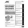
2.3 DISASSEMBLY/ASSEMBLY OF MECHANISM ASSEMBLY 2.3.1 General statement The mechanism should generally be disassembled/assembled in the EJECT mode (ASSEMBLY mode). (Refer to Fig. 2-3-1.) However, when the mechanism is removed from the main body, it is set in the STOP mode. Therefore, after the mechanism is removed from the main body, supply 3 V DC to the electrode on the top of the loading motor to enter the mechanism mode into the EJECT mode compulsory. <Mechanism assembly/Cassette housing assembly>
DC3V
<SUB CAM GEAR>
TOP VIEW
BOTTOM VIEW
Fig. 2-3-2
<EJECT mode>
Fig. 2-3-3
Motor
<C IN mode>
Fig. 2-3-4
<SHORT FF mode>
Fig. 2-3-5 <Back side of the mechanism assembly>
<STOP mode>
Fig. 2-3-6
EJECT mode Back side of deck
<REV mode>
Fig. 2-3-1 2.3.2 Explanation of mechanism mode The mechanism mode of this model is classified into six modes as shown in Table 2-3-1. Each mechanism mode can be distinguished from others by the relative position of � � mark on the sub cam gear to the inner or outer protrusion on the main deck. Refer to Fig. 2-3-2 to 2-3-8 below. The EJECT mode, C IN mode and SHORT FF mode should be recognized by the relative position of the � � mark to the inner protrusion, while the STOP mode, REV mode and PLAY mode should be recognized by that to the outer protrusion. Fig. 2-3-8 2-3
Fig. 2-3-7
<PLAY mode>
|