|
|
|
Categories
|
|
Information
|
|
Featured Product
|
|
|
 |
|
|
There are currently no product reviews.
 ;
A good manual! fast service and good qualityi for pdf document.
thanks!
 ;
Very helpful and complete manual. Maybe only one negative is schematics have sometimes unreadable name of the parts. But it's not a big problem.
;
Excellent high quality schematics brought my old Heidelberg back to life. Fast download at a reasonable price. Thanks.
;
This document is just what I was looking for, it´s very useful, it contains adjustment procedures for the final stage of the power amp and also
has a complete wiring diagram and description of the main semiconductors used in the design.
;
Dear Sirs,
Thank you for the fast support, the manual does provide all necessary information to repair the radio. All schematics are in a good quality for reading.
The manual fits 100% to my requirements as a technican.
Kind regards Thomas
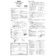
2.5 CHECKUP AND ADJUSTMENT OF MECHANISM PHASE
<Rotary encoder> Set the �I� of the rotary part at the tapped hole as shown in the figure.
<Connect gear> (Note 2) Set the connect gear so that its locating hole meets the hole on the main deck assembly.
<Worm wheel> (Note 2) Set the worm wheel so that its locating hole meets the hole on the main deck assembly.
Note 1 <Main cam gear /Brake control plate> After fitting the main cam gear and brake control plat together,set them together so that their locating holes meet the hole on the main deck assembly.
<Connect gear 2> (Note 2) Set the connect gear 2 so that its locating hole meets the hole on the main deck assembly.
<Sub cam gear> Set the sub cam gear so that its locating hole meets the hole on the main deck assembly. This state represents that the mechanism is in the EJECT mode, which is the �mechanism assembly mode�.
Note 1: Since the connect gear 2 is tightly fixed to the main deck by caulking, adjust its phase with the connect gear and sub cam gear.
Note 2: The part that needs phase adjustment by the hole on the main deck assembly must exactly be set as the specified phase. There is a fear that some part is installed in a wrong phase because assembling of the mechanism is automated. If so, set every part in the correct phase whenever the mechanism is reassembled.
Fig. 2-5-1
2-15
|
|
|
> |
|