|
|
|
Categories
|
|
Information
|
|
Featured Product
|
|
|
 |
|
|
There are currently no product reviews.
 ;
Je suis audiophile belge, électronicien et créateur d'enceintes acoustiques.
J'ai apprécié la qualité des documents fournis. Ils sont très lisibles, ils peuvent être agrandis sans problème et ils sont complets. Pour moi, c'est parfait. Pour cette qualité, je suis d'accord de payer. Et le système de paiement et d'envoi est simple. Merci, continuez comme cela.
Frédéric
;
The cover page was a little scary, very dark but readable. The remainder of the document was better copy and easily readable. Why would I give 5 Stars? (1) PRICE, (2) AUTHENTICITY, It was the real deal, filled with service information, including the specific information I required. (3) PRIVACY, I didn't start to get slammed with spam. (4) EASY TRANSACTION. Painless. (5) COMPLETE, I have found several manuals here, that I could find nowhere else. (6) I will be a repeat customer!
;
Well done!!! I found what I need to have, indeed!
Furthermore, due to my hobby is repairing vintage equipments, I added this web site in my desk toolbar because I have in mind to search further service manuals. Thanks a lot www.owner-manuals.com !
Regards, Maurizio
;
Again very good service manual, this time very fast download. AAAAA+
;
Ckear manual, well reproduced with plenty of overlap on critical pages.
BACK TENSION 0.97x10 -3 - 1.71x10⁻³ N�m (10-17gf·cm) PLAY TORQUE 1.47x10⁻³ - 2.45x10⁻³ N·m (15-25gf·cm)
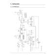
NOTE: To prevent the tape from damage, turn the guide rollers slowly. (7) By operating the tracking button (both in + and - directions) in the manual tracking mode, vary the output level of the FM waveform from maximum to minimum and vice versa to confirm that the waveform varies nearly in a flat shape. (8) When the FM waveform breaks in the level varying process, subtly adjust the height of guide rollers at every breaking point so that the waveform varies as flat as possible. Repeat the above steps 6. and 7. several times to confirm that the waveform is flat as a whole. (9) Playback the SP stairstep signal of alighment tape and adjust the tracking control to maximize the FM waveform, confirm that FM waveform variation is always flat. (10) Record the signal and play it back in both of the SP and EP modes, and confirm that the FM waveform is flat in both modes. NOTE: Among the above-mentioned adjustment steps, the items of No.9 and No.10 are needed for the EP model only.
Fig.3-3-3 3.3.3 Tape pattern Remove the exterior parts attached to the UPPER CASE ASSEMBLY so that the guide roller beside the DRUM ASSEMBLY can be rotated. � LOWER CASE ASSEMBLY � TOP OPE UNIT � CASE COVER(S),(M) ASSEMBLY � UPPER CASE (S),(M) ASSEMBLY NOTE: In performing adjustment, it is recommended that LOWER CASE ASSEMBLY and TOP OPE UNIT are attached to the main body for better operation and safety. POLE BASE (TU) (GUIDE ROLLER)
CH-2 1 field
FLATTEN WAVEFORM.
ALIGNMENT TAPE
CAUSER BY WRONG HEIGHT OF SUPPLY GUIDE ROLLER
CAUSED BY WRONG HEIGHT OF TAKE-UP GUIDE ROLLER
Fig.3-3-5
CORRECT VARIATION OF WAVEFORM
BAD VARIATION OF WAVEFORM
POLE BASE (SUP) (GUIDE ROLLER)
JIG CONNECTOR CABLE MAIN CN25 - JIG BOARD 12PIN(V_TP_FM) 13PIN(V_FF)
Fig.3-3-6 (11) Through the above steps, confirm that there occur no wrinkling and damage in the tape around the PINCH ROLLER and TU GUIDE POLE whenever the deck is in operation of Loading/Unloading, Search Rewind and at mode change from Search Rewind to play mode. If wrinkling or damage in the tape occurs around the TU GUIDE POLE, adjust the angle (slant) of the A/C HEAD to the tape. So that the tape normally runs along the lower flange of the GUIDE POLE.
(1) (2) (3) (4) (5)
(6)
Fig.3-3-4 Remove the Cover (JIG) shown on Fig.3-4-1. Connect the JIG CONNECTOR CABLE to CN25 on the MAIN BOARD ASSEMBLY as shown on Fig. 3-2-2. Observe signal at V_TP_FM with external trigger from V_FF on the JIG CONNECTOR CABLE. Playback the SP stairstep signal of the alignment tape and maximize the FM waveform by the tracking button. Set the tracking control to the center position by simultaneously pressing the tracking (-) and (+) buttons and maximize the FM waveform by the tracking button. If the observed FM waveform is not flat, adjust the height of the SUPPLY of TAKE-UP GUIDE ROLLER with the roller driver.
3-4
|
|
|
> |
|