|
There are currently no product reviews.
 ;
Manual was reasonably easy to follow. I am not an engineer or know much about electronics but with the manuals help I was able to figure out the problem, identify the part required for the repair. Replacement part cost around $30. Whilst replacing the part I was telling myself, "this aint gonna work cos it seems far too easy". Took about 15 minutes to do and my plasma TV works a treat. Would never have been able to do this without the service manual.
;
It is OK, this manual help me to repair my dynacord
 ;
Good manual. Even it is an old printed manual, it is well scanned and complete, with all drawings, schematics and parts list. Very good return for the cost.
;
I'm very satisfied with my purchase. It resolved my problem. Owner-manuals.com is a very very good place.
Thank you!
;
Veramente completo, dettagliato e perfetto nella visione. Perfect, thanks!
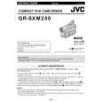
2.8 TAKE OUT CASSETTE TAPE In the event that the set enters the emergency mode as it is loaded with a cassette tape and the cassette tape cannot be ejected with the EJECT button, manually, take it out of the set according to the following procedure. NOTE : � If the mechanism comes into the unloading mode as the cassette tape is not held by hand, it results in tape damage. (1) Disconnect the set from the power source. (2) Remove the LOWER CASE ASSEMBLY and TOP OPE UNIT (see Fig.C1, page 6). (3) Connect a jumper wire to each pole of the LOADING MOTOR as shown by the magnified view (Fig. 2-8-1). (4) While holding down the cassette housing by hand, connect the jumper wires to a battery to run the mechanism to the EJECT position four unloading. If this unloading operation is performed as the cassette housing is not held down by hand, the front lid of the cassette may damage the tape when it is ejected. (5) For taking in the slack of the tape, run the mechanism to the EJECT position as the front lid of the cassette is left open, and turn the TAKE-UP GEAR in the forward direction to wind up the tape. After confirming that the tape has completely been wound up and the supply reel is idling, take the cassette tape out of the cassette housing.
BATTERY
(DC1.5V)
MAGNIFIED VIEW b
TAKE-UP GEAR
Fig.2-8-1
(No.86721)1-17
|