|
|
|
Categories
|
|
Information
|
|
Featured Product
|
|
|
 |
|
|
There are currently no product reviews.
 ;
The service manual is a good quality scan of the Panasonic NV-850, which is electrically identical to the Philips VR 6920, but mecanically just nearly.
;
The service manual is a good quality scan of the Blaupunkt RTV-404, which is electrically and mecanically identical to the Panasonic NV-830.
;
completo manual bien detallado y de buena calidad de impresion , se echa en falta los esquemas de placa y parte de algun diagrama.
 ;
perfecto manual ,completo y detallado de muy buena calidad de impresion, ideal en una palabra.
;
un manual completo con una calidad de imagen buena con explicaciones en varios idiomas de los ajustes y detalles en conjunto un OK.
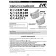
1.5 REPLACEMENT OF CCD IMAGE SENSOR Notes: � Pay the most careful attention to the transparent glass and optical LPF of the CCD image sensor so a not the soil and damage them. If something is soiled with finger-prints, etc., gently clean it with silicon-processed paper/cloth or chamois. � When the CCD image sensor is shipped from the factory, there are protection seals applied onto the transparent glass. Leave the protector as it is, and take it off just before assembling the CCD image sensor to the OP block. 1.5.1 Removal of CCD image sensor 1. Remove two screws (1, 2) securing the CCD base assy, and disassemble the CCD spacer, the optical LPF, spacer rubber. 1.5.2 Installation of new CCD image sensor 1. Remove the protection seal from a new CCD image sensor. Next, put the optical LPF, spacer rubber, CCD spacer on the CCD image sensor as they are piled up in this order. At that time, make sure of orientation of each item refering to the following table (see Fig. 1-5-1).
Part Name CCD image sensor Spacer rubber Optical LPF
Orientation Mark is on the right viewed as indicated by the arrow a . IC side is horizontal. Marks are on the left and bottom viewed as indicated by the arrow a.
2. Fix the CCD base assy to OP block with the two screws (1, 2) . At that time, be careful of the orientation. 3. After completion of all P.C. boards to the camera section, observe the monitor to confirm no vignetting caused by the bodytube, rings, lens hood, etc. If no vignetting is observed, it can be said that image's parallel, horizontality and centering are correct. 1.5.3 Replacement of CCD board assy 1. Remove one screw (3). 2. Unsolder at the fourteen points on the CCD board assy. Note: 1. Remove the screw (3) only when the CCD board assy needs replacement. 2. When installing a new CCD board assy, carry out the above-mentioned procedure in the reverse order.
a
OPTICAL LPF
1
BLUE CCD SIDE
(S 1 b) 2
CCD BOARD ASSEMBLY
�3
(S 1 a)
OP SIDE
(S 1 a)
CCD BASE ASSEMBLY CCD SPACER SPACER RUBBER
� : 0.147 N�m (1.5 kgf�cm)
Fig. 1-5-1 1-12
|
|
|
> |
|