|
|
|
Categories
|
|
Information
|
|
Featured Product
|
|
|
 |
|
|
There are currently no product reviews.
 ;
Thanks God for the internet and thanks for the service like this - proffessional solution on time.
;
About the service it's very fast and reliable. About the manual the quality is high enough to read even the tiniest details on the wiring diagrams so you can't ask much more than that, let it alone for a manual of a product from 20 years ago. Thank you, very satisfied.
;
The downloaded quality was as good as the orignial
 ;
This is a great and complete Service Manual for the Sharp GF8585HB. Giving full and detailed technical insight. Good to find these manuals online.
;
Everything was ok with the manual. If I have a small complaint, is that I ordered it during the weekend and I think you guys were closed. But I did receive it late Sunday. I will surely order from you again
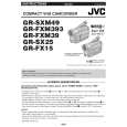
2.8 TAKE OUT CASSETTE TAPE In the event that the set enters the emergency mode as it is loaded with a cassette tape and the cassette tape cannot be ejected with the EJECT button, manually, take it out of the set according to the following procedure. NOTE : � If the mechanism comes into the unloading mode as the cassette tape is not held by hand, it results in tape damage. (1) Disconnect the set from the power source. (2) Remove the LOWER CASE ASSEMBLY and TOP OPE UNIT (see Fig.C1, page 6). (3) Connect a jumper wire to each pole of the LOADING MOTOR as shown by the magnified view (Fig. 2-8-1). (4) While holding down the cassette housing by hand, connect the jumper wires to a battery to run the mechanism to the EJECT position four unloading. If this unloading operation is performed as the cassette housing is not held down by hand, the front lid of the cassette may damage the tape when it is ejected. (5) For taking in the slack of the tape, run the mechanism to the EJECT position as the front lid of the cassette is left open, and turn the TAKE-UP GEAR in the forward direction to wind up the tape. After confirming that the tape has completely been wound up and the supply reel is idling, take the cassette tape out of the cassette housing.
BATTERY
(DC1.5V)
MAGNIFIED VIEW b
TAKE-UP GEAR
Fig.2-8-1
1-16 (No.86712)
|
|
|
> |
|