|
|
|
Categories
|
|
Information
|
|
Featured Product
|
|
|
 |
|
|
There are currently no product reviews.
 ;
This is quiet a rare manual, I Have looked for this manual for quiet a while now, I have finally found it here. I believe this is the only place they have them in a very nice scan, Excellent guide: very clear, enabling us to print readable diagram overall it is great to have this manual available for purchase. This is a complete service manual no pages are missing. Thanks
;
This SM is quiet scarce and hard to find it is an excellent Service manual, very clear to read and to print schematics and diagrams, Hi quality, Complete manual with no pages missing. I am very pleased with the manual and the fast service I have received. Great place to shop.
Good luck finding you manual...
;
Quick delivery, the document was usefull, although the copy was i little bit unclear in the details.
 ;
A complete and well done copy of the manual, at a not expansive price!
The delivery of the manual is very fast.
Thank you for all
;
Perfect quality. Was able to fix speed drifting on my Sansui Turntable using the service manual instructions for PLL adjustment.
GV 32�, GV 52�, GV 62�
Drive Mechanism
3. Disassembly Instructions
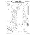
3.1 Loading motor � Undo the screw A (Fig. 3). � Remove the loading motor (B410, Fig. 3) to the rear. Fig. 6
K530 G546
H
B410
A
B448 B452
Fig. 7
B452
Fig. 3
K470
A B448
3.5 AC combi head � Undo the plug connectors if necessary. � Undo the screw I (Fig. 8) then remove the AC combi head (G480). Reassembly is carried out in reverse order. Note on reassembly: � After replacing the combi head all adjustments described in the points 4.2, 4.3 and 4.4 must be carried out.
3.2 Cassette lift � Move the drive mechanism to the "Eject" position for removing the cassette lift: � Remove the loading motor (point 3.1). � Turn the white gear joint (B448, Fig. 3) counterclockwise until the cassette lift is in the "Eject" position. � Tense the spring-loaded lift lever B (Fig. 4), release the catch C then remove the cassette lift (K490, Fig. 1). Note on reassembly: � Insert the cassette lift so that the two left guide pins D (Fig. 5) engage into the lift guides of the lift lever (K530) and in the frame. � Tense the spring-loaded lift lever B (Fig. 4), release the catch C then insert the cassette lift into the right guide of the lift lever.
I
G480
A B
K
C
C
Fig. 8
D E F B Fig. 4 Fig. 5
B560
K490 K530
3.3 Lift lever � Remove the cassette lift (point 3.2). � Disengage the locking lug of the lift lever one after the other through the holes E (Fig. 5) and F then remove the lift lever (K530). 3.4 Lift drive � Remove the lift lever (point 3.3). � Slide the lift slider (K470, Fig. 3) to the cam wheel (B452) and remove the door opening lever (546). � Slide the lift slider (K470, Fig. 3) to the front then remove it. � Remove the black cam wheel (B452, Fig. 3) and the white gear joint (B448). Note on reassembly: � Insert the white gear joint (B448, Fig. 3). � Insert the cam wheel (B452, Fig. 7) with the drive mechanism in unthread position so that the mark A points towards the shaft of the white gear joint (B448). � Insert the lift slider (K470, Fig. 3), press on the cam wheel (B452) then slide it backwards. � Insert the door opening lever (G546) so that the guide of the right side part engages into the guide groove H (Fig. 6). � Reassembly is carried out in reverse order.
3.6 Capstan motor � Remove the reel belt (G542, Fig. 2). � Undo the plug connectors if necessary. � Undo the 3 screws K (Fig. 8). � Remove the capstan motor (B560, Fig. 8) from the drive mechanism. Make sure that the capstan does not touch greased parts of the drive mechanism. Reassembly is carried out in reverse order. Make sure that the capstan is free of grease (clean it if necessary). 3.7 Tape drum unit � Undo the plug connectors if necessary. � Undo the 3 screws L (Fig. 9). � Remove the ground plate (Fig. 9). � Remove the tape drum unit (G001, Fig. 9) carefully from the drive mechanism. Reassembly is carried out in reverse order. Adjustments and checks after replacement � Check the tape transport (point 4.7.3). � Adjust the tape drum position indicator (Adjustment No.1, page 2-2).
GRUNDIG Service
4-7
|
|
|
> |
|