|
|
|
Categories
|
|
Information
|
|
Featured Product
|
|
|
 |
|
|
There are currently no product reviews.
 ;
Fast delivery and good quality copy. To be recommended
;
Excellent product, very clear print. Detailed circuit and assembly diagrams - this enabled me to repair my CD player with confidence. I highly recommend this site.
;
Fast access, 100% correct and complete service manual
;
just what i was seeking .had a password issue but the review allowed me to circumvent and download was great
;
Great manual, great price. Has a few of the basic operating instructions that most service manuals leave out. Complete instructions for disassembling board by board, safety precautions, schematics, complete parts list.
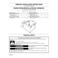
GV 31�, GV 51�, GV 61�
Drive Mechanism
Fig. 13
B456 B500
Q
B458 B464
J KI L
Fig. 17
B488
K200 K221
B484
EGHF R
R
B468 K340 K330 B478
3.16 Threading roller unit � Release the locking lug P (Fig. 11) then remove the loading drive gear (B484, Fig. 2). � Slide the threading roller units (G420 / G450, Fig. 18) in the "Thread" position then remove the threading arms (B500 / B488). � Remove the left reel brake (point 3.10). � Slide the right threading roller unit (G450, Fig. 19) in threading direction then remove it. � Remove the back tension arm (point 3.11). � Slide the left threading roller unit (G420, Fig. 19) in unthreading direction then remove it. Reassembly is carried out in reverse order. Note on reassembly: � Insert the threading arms so that the holes M / N (Fig. 18) face each other in the "Thread" drive mechanism position. � Insert the loading drive gear (B484, Fig. 13) in the "Unthread" drive mechanism position so that the hole I and the mark J on the threading arm face each other as shown in Fig. 13, and the mark L on the control slide (B464) is visible through the hole K. Press the control slide against the guides R then lock in the loading drive gear (B484).
G450 G420
X
X
X
X
3.14 Idler wheel � Remove the reel brakes (point 3.9 / 3.10). � Slide the idler wheel (K182, Fig. 14) towards the rear of the drive mechanism then remove it. Reassembly is carried out in reverse order.
K188
K182
K188
Fig. 14
MN
Fig. 18
B500 B488
3.15 Gear drive � Remove the idler wheel (K182) (point 3.14) � Remove the right reel. � Remove the reel belt (G542, Fig. 2). Remove the lock washer S (Fig. 15). Remove the pulley (K200, Fig. 15). Remove the control slide (point 3.13) Release the locking lugs T (Fig. 15) then remove the gear drive (K221). Reassembly is carried out in reverse order. Note on reassembly: � The slide disk of the gear drive (K221, Fig. 16) must be located in the guide U of the switching claw (K225) when reassembling. � The pulley (K200, Fig. 17) must be inserted so that the spring is located in the opening of the slide disk. S K222
K200
3.17 Full erase head � Turn the full erase head (G530, Fig. 19) counterclockwise then remove it.
� � � �
G530 G420 G450
Fig. 19
K225
T Fig. 15
K221
3-18 Tape reverse guide lever � Remove the pinch roller unit (point 3.8). � Unhook the spring G527 (Fig. 20). � Turn the tape reverse guide lever (G520, Fig. 20) in direction of the arrow "A" then remove it in direction of the arrow "B". Reassembly is carried out in reverse order.
"A" G527 G520 "B"
K221
U
35°
K225
Fig. 20
Fig. 16
GRUNDIG Service
4-9
|
|
|
> |
|