|
|
|
Categories
|
|
Information
|
|
Featured Product
|
|
|
 |
|
|
There are currently no product reviews.
 ;
Perfect source for service manuals: fast and professional transaction; high quality, perfect readable and largely scaleable PDF; complete schemes, diagrams and spare part list. Tnx a lot, cu again!!!!
;
I got your link from a friend and I must say that I am really satisfied with your service. Specially this B&O manual I didn't find anywhere on the web... but you could deliver it :-) . You deliver very fast and the copy is of good quality. So your webpage is bookmarked. Thanks
;
This was the Sony CCU-500A Service manual I was looking for.
The price was reasonable.
The permission to download was quck.
I will use Owner-Manual.com for all my manual needs.
;
Excellent printing quality.
A complete and very usefull service manual with all details.
GREAT SERVICE AT VERY LOW PRICE!
A+++++++++++++++++++++++++
;
Excellent printing quality.
A complete and very usefull service manual with all details.
GREAT SERVICE AT VERY LOW PRICE!
A+++++++++++++++++++++++++
Platine mécanique
GV 29 EURO, GV 9300 EURO
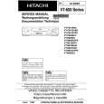
Note: Lors du remontage du tambour de bande (Pos. 11000) aligner celui-ci avec les deux goujons Y sur la surface de montage du cadre du mécanisme d'entraînement (Fig. 8.39). Serrer les vis (Pos. 10400) avec un couple de 3.9 à 4.2 kg/cm.
9. Réglages
9.1 Réglage du ruban de freinage � Activer le mode d'essai service (voir point 6) et amener le mécanisme d'entraînement dans la position PLAY/STOP (l'afficheur indique 05). � Ajuster la languette d'ajustage du ruban de freinage A de sorte à ce que le bout du levier (Pos. 40100) se trouve entre les repères sur le cadre du mécanisme d'entraînement (Fig. 9.1). Contrôle de la tension de bande: � Lire la cassette de couple dans le mode PLAY. � Le couple de tension de bande doit être 30�50g/cm.
11000 Tambour de bande cpl
Le bout du levier doit se trouver entre les deux lignes
Y Goujons
10400 Vis 10400 Vis
A
Fig. 8.38 Note: Après le montage du rotor (Pos. 21000) il faut aligner la phase suivant la phase du tambour de têtes. Le trou W dans le tambour de têtes et le trou X dans le rotor (Pos. 21000) doivent se trouver sur le même côté comme montré à la Fig. 8.38. Serrer les vis (Pos. 30000) pour le rotor moteur (Pos. 21000) et le stator moteur (Pos. 22000) avec un couple de 2.5 à 3.5 kg/cm. Fig. 9.1
9.2 Contrôle du couple des plateaux porte-bobine (Fig. 9.2) � Démonter le compartiment cassette (voir point 8.1). � Couvrir les capteurs de début et de fin de bande. � Poser le couplemètre avec adaptateur sur le plateau porte-bobine gauche ou droit et le mettre à zéro. � En mode �, mesurer le couple du plateau d'enroulement après 10 secondes. Il doit se situer entre 60 et 110g/cm. � Appuyer sur la touche � pendant la fonction PLAY. Mesurer le couple du plateau débiteur. Il doit se situer entre 115 et 180g/cm.
11200 Tambour de têtes
W Trou
21000 Rotor moteur
X Trou
Fig. 8.39
Fig. 9.2
5 - 14
GRUNDIG Service
|
|
|
> |
|