|
|
|
Categories
|
|
Information
|
|
Featured Product
|
|
|
 |
|
|
There are currently no product reviews.
 ;
I buy the service manual cheaper here than in elsewhere.Am happy with this site. I recommended the Owner-Manuals.com
;
Great Manual. It was exactly what I was looking for
;
Great Manual. It was exactly what I was looking for
;
I am really satisfied. It was ceap, easy and quick. Te owner manual is a full service book. I got what I expected. Thx
;
The service was good but it just a little late for the download. It seems that it needs to clear the payment but the payment was settled by paypal. As far as my concern, it should be able to download after the confirmation of sold.
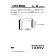
PURITY CONVERGENCE ADJUSTMENT
NO. Adjustment part Adjusting procedure conditions Waveform and others
PURITY ADJ. GREEN-ONLY Adjust 1 CONVERGENCE 1. Receive the "Crosshatch Pattern" signal. BGR
beam current to ~ 700 µA. ADJ. 2. Using the remote controller, call NORMAL
R 3. Maintain purity magnet at the zero magadjustment.) Static convergence
2. Degauss CRT enough with the degausing (To be done mode. B
coil. a b G after the purity
4. Observe the points a, b, as shown in Fig. 1-1 colours. Fig. 1-1 A rank requirement. angle in order to superpose the green colour
G
netic field and keep static convergence 1. Turn the 4-pole magnet to a proper opening roughly adjusted. angle in order to superpose the blue and red Fig. a
RGB through microscope. Adjust the landings R 5. Orient raster rotation to 0 eastward. over the blue and red colours.
2. Turn the 6-pole magnet to a proper opening
6. Tighten up the deflection coil screws. B
» Tightening torque: 108N ± 20 N Dynamic convergence
7. Make sure CRT corners landing meet screen in the following steps. Fig. b
(11kgf ± 2 kgf) 1. Adjust convergence on fringes of the A
B
A rank requirements. If not, stick magnet RGB a) Fig. a : Drive the wedge at point "a" and sheet to correct it. B swing the deflection coil upward. G Note:This adjustment must be done after b) Fig. b : Drive the wedge at point "b" and "c" R warming up unit for 30 minutes or and swing the deflection coil downward. longer with a beam current over 700 c) Fig. c : Drive the "c" wedge deeper and
A = B µA.
swing the deflection coil rightward. Fig. 1-2
R G
* For following colours press R/C RGB key to d) d : Drive the "b" wedge deeper and Fig. c
(on right of the CRT)
change. Rank "A" swing the deflection coil leftward. BGR 3. Apply lacquer to the deflection yoke lock screw,
A
2. Fix all wedges on the CRT and apply glass tape over them. B magnet unit (purity, 4-pole, 6-pole magnets) and magnet unit lock screw. Fig. d Green-only Blue-only Red-only
7
B on the screen.
Finally received the Red-only and Blue-only signals to make sure there is no other colours Wedge "a"
screen cleared
A = B
Signal-colour About 100°
4-pole magnet 6-pole magnet CRT neck Fig. 1-3
Lacquer
(on left of the CRT) Wedge
Rank "A"
"b" "c"
* Press R/C RGB key for 1 second in NORMAL MODE, the colLacquer our will change to RGB mono Purity magnet colour mode.
20mm
21GT-22
7-1 7-2
|
|
|
> |
|