|
|
|
Categories
|
|
Information
|
|
Featured Product
|
|
|
 |
|
|
There are currently no product reviews.
 ;
I really like this manual and it's reliable.I found and bought easly.thank you.
;
Thank you very much. the Instruction corresponds to my expectations. Sent it in time. I don't regret that paid money.
;
Good quality. Quick service. I recommend to everyone.
;
Very good quality scan of the document. I am very pleased with what I got.
;
PDF Contains
Technical Data, Mechanical data, Detailed Circuit diagram with components value, PCB layout. Actual PCBs Print. Component List, Spare parts code list and Input output detail. It cover LBB1211, LBB1212, LBB1213, LBB1216, LBB1217.
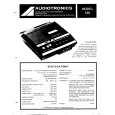
It is the actual Service Manual for SQ10
5.
TEMPERATURE COMPENSATION OFFSET ADJUSTMENT
6.
LASER POWER ADJUSTMENT
laser power meter
Connection:
Save the temperature data at that time in the non-volatile memory as 25°C reference data.
Notes: 1. Usually, do not perform this adjustment. 2. Perform this adjustment in an ambient temperature of 22 °C to 28 °C. Perform it immediately after the power is turned on when the internal temperature of the unit is the same as the ambient temperature of 22 °C to 28 °C. When D101 has been replaced, perform this adjustment after the temperature of this part has become the ambient temperature.
Optical pick-up objective lens
3.
digital voltmeter BD (MD) board TP29 (IOP +) TP30 (IOP �)
+ �
Adjusting Method: 1. Turn the MULTI JOG dial and display �TEMP ADJUST�. 2. Press the ENTER/YES button and select the �TEMP ADJUST� mode. 3. �TEMP = � and the current temperature a data will be displayed. 4. To save the data, press the ENTER/YES button. When not saving the data, press the EDIT/NO button. 5. When the ENTER/YES button is pressed, �TEMP= SAVE� will be displayed for some time, followed by �TEMP ADJUST�. When the EDIT/NO button is pressed, �TEMP ADJUST� will be displayed immediately. Specifications: The temperature should be within �E0-EF�, �F0-FF�, �00-0F�, �10-1F� and �20-2F�.
Adjusting Method: 1. Set the laser power meter on the objective lens of the optical pick-up. (When it cannot be set properly, press the ) button or 0 button and move the optical pick-up.) Connect the digital voltmeter to CN110 pin 5 (I+3 V) and CN110 pin 4 (IOP) of the BD (MD) board. 2. Turn the MULTI JOG dial and display �LDPWR ADJUST�. (Laser power: for adjustment) 3. Press the ENTER/YES button and display �LD 0.9 mW $ �. 4. Turn the MULTI JOG dial so that the reading of the laser power meter becomes 0.82 to 0.93 mW. Set the range control on the laser power meter to 10 mW, then press the ENTER/YES button to save the adjustment result in the non- volatile memory. (�LD SAVE $ � will be displayed for a moment.) 5. Then �LD 7.0 mW $ �will be displayed. 6. Turn the MULTI JOG dial so that the reading of the laser power meter becomes 6.9 to 7.1 mW, press the ENTER/YES button and save the adjustment result in the nonvolatile memory. (�LD SAVE $ � will be displayed for a moment.) Note: Do not perform the emission with 7.0 mW more than 15 seconds continuously. 7. Turn the MULTI JOG dial and display �LDPWR CHECK�. 8. Press the ENTER/YES button and display �LD 0.9 mW $ �. Check that the reading of the laser power meter becomes 0.80 to 0.96 mW. 9. Press the ENTER/YES button and display �LD 7.0 mW $ �. Check that the reading of the laser power meter and digital voltmeter satisfy the specified value. Specification: Laser power meter reading : 7.0 ± 0.2 mW Digital voltmeter reading : Optical pick-up displayed value ±10%
(Optical pick-up label)
KMS260A 27X40 B0567
lOP=56.7 mA in this case lOP (mA) = Digital voltmeter reading (mV)/1 (�)
10. Press the EDIT/NO button and display �LDPWR CHECK�, and stop the laser emission. (The EDIT/NO button is effective at all times to stop the laser emission.)
� 25 �
|
|
|
> |
|