|
|
|
Categories
|
|
Information
|
|
Featured Product
|
|
|
 |
|
|
There are currently no product reviews.
 ;
This is the correct service manual of SHARP RX-100H(BK) DAT.
;
The ervice manual for my 1982 Kenwood KR-1000 receiver is great! Full detail on all circuits with part number detail. I will definately be ordering more manuals for my other vintage equipment! Order was fulfilled quickly! Very efficient ordering process! Thnaks for your help! Great site!
 ;
Everything in the manual was excellent except for a couple of pictures of specific areas in the unit that were a little dark. Owners Manuals re-sent the pdf file & the problem was corrected. Excellent product! George
;
Thanks for offering this item at such a good price. Proved handy in identifying the part I was looking for my set.
Thanks again.
;
This is the original manufacturers service manual, with detailed info on the circit boards, explosion drawings of all parts in assembly order, and tuning instructions. The only thing missing is the information on the dimensions of the various drive belts. mail me if you need them. gcrossman_at_aol.com
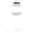
DISASSEMBLY ADVICE CAPS OPERATION KNOBS 1 SWITCH KNOB 2 THERMOSTAT KNOB 3 SWITCH 4 THERMOSTAT 5 PILOT LIGHT 9
remove SCREW A (4x) remove FRONT PART 101 remove CAPS OPERATION KNOBS 2
PARTS LIST HD 3274 / HD 3275 STAND 102 POS. 1 2 3 4 5 6 7 8 9
NOTE: For standardisation reasons, only the red-coloured operation knobs have been incorporated into this manual. The dark blue coloured knobs have to be replaced by the red-coloured ones. When a cordset has to be replaced, always use a cordset with 2. core wires with a diameter of 1.0 mm Parts, with numbers from 100 upwards, cannot be ordered separatly.
DESCRIPTION CAP OPERATION KNOBS SWITCH KNOB THERMOSTAT KNOB SWITCH THERMOSTAT HEATING ELEMENT MOTOR FAN BLADE PILOT LAMP
SERVICE CODE 4822 462 10812 4822 410 10791 4822 410 10792 4822 273 10319 4822 282 10299 4822 259 10212 4822 361 10521 4822 515 20148 4822 134 10056
MOTOR 7 HEATING ELEMENT 6
4
remove SCREW A 4x remove FRONT PLATE 101 remove SCREW B 2x
L
1000 W 3
2 1000 W M
FAN BLADE 8
remove SCREW A 4x remove FRONT PLATE 101
S
1
P. L.
N T C. O.
L N T C. O.
= LINE = NEUTRE = THERMOSTAT (Not included in HD3271) = CUT OUT
P. L. = PILOT LIGHT (Not included in HD3271) S = SWITCH M = MOTOR DAP0244
NOTE:
AFTER THE PRODUCT HAS BEEN REPAIRED, IT SHOULD FUNCTION PROPERLY AND HAS TO MEET THE SAFETY REQUIREMENTS AND LEGAL REGULATIONS AS LAID DOWN AND OFFICIALLY ESTABLISHED AT THIS MOMENT.
Possible complaints The heater doesn�t function : 1) When set to the cool air setting action: Set the thermostat knob to the highest position. 2) The overheating safety device has been activated action: To reset the overheating device, remove the mains plug from the wall socket and let the heater cool down for 30 minutes.
|
|
|
> |
|