|
|
|
Categories
|
|
Information
|
|
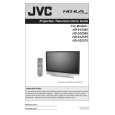
Featured Product
|
|
|
 |
|
|
There are currently no product reviews.
 ;
The manual is useful for trouble shooting for an old instrument. It saved money,and let me enjoy DIY.
 ;
Perfect source of information for replacing the HDD and performing general diagnostics.
;
Perfect source of information for replacing the HDD and performing general diagnostics.
;
Very good scanned copies. Quick response and reasonable price. Thanks for service!
;
Good. Good. Good. Good. Good. Good. Good. Good. Good. Good. Good. Good. Good. Good.
SECTION 3 DISASSEMBLY
3.1 DISASSEMBLY PROCEDURE � Make sure that the power cord plug is pull out from the AC wall outlet. � Wait until the LAMP UNIT has cool down is completely. � While not in repair service, place the chassis back its original position. 3.1.5 FRONT LED PWB � Take out the SPEAKER GRILL. � Take out the FRONT PANEL. (1) Remove 2 screws [ F ] from rear side of FRONT PANEL. (2) Take out the FRONT LED PWB. 3.1.6 FILTER COVER � Take out the SCREEN BLOCK. (1) Remove 2 screws [ G ]. (2) Take out the FILTER COVER. � Remove the both side FILTER COVER same manner. 3.1.7 CENTER COVER � Take out the SPEAKER GRILL. � Take out the FRONT PANEL. (1) Remove 2 screws [ H ]. (2) Take out the CENTER COVER. 3.1.8 SCREEN BLOCK
Masking tape
CAUTION AT DISASSEMBLY
� Pay extra attention in the following matter when turning the power on with the BODY COVER removed. (1) Prior to disassembly, unplug the power cord from the AC outlet without fail. (Turn the power "off".) (2) Make sure that the REAR JACK PWB: IC2081 is completely covered with black masking tape. (Fig.1) (3) Make sure to remove the masking of REAR JACK: IC2081 when attaching the BODY COVER. (4) Do not turn the power on until the BODY COVER is attached properly, after the masking is removed.
REAR JACK PWB
IC2081
� Take out the SPEAKER GRILL. � Take out the FRONT PANEL. (1) Remove the 4 screws [ I ]. (2) Remove 10 screws [ J ] from rear side. (3) Take out the SCREEN BLOCK. CAUTION : � Place the SCREEN BLOCK on a flat table without fail. � Because of the large size, at least 2 parsons are recommended for removal and reassemble. � Use care not to scratch the screen during work. � During assembly, be sure to engage the left and right tabs with the cabinet mounting positions. � When supporting the SCREEN BLOCK, avoid grasping the top of the screen panel, instead grasp the left and right areas. � Do not leave the SCREEN BLOCK removed for long time to prevent soiling from dust. 3.1.9 SCREEN ASS�Y � Take out the SCREEN BLOCK. [HD-52Z575 / HD-52Z585] (1) Remove 20 screws [ K ] from FRONT CABINET. [HD-61Z575 / HD-61Z585] (1) Remove 24 screws [ K ] from FRONT CABINET. (2) Take out the SCREEN ASS�Y. 3.1.10 FRONT PANEL � Take out the SCREEN BLOCK. [HD-52Z575 / HD-52Z585] (1) Remove 16 screws [ L ] from FRONT CABINET. [HD-61Z575 / HD-61Z585] (1) Remove 20 screws [ L ] from FRONT CABINET. (2) Take out the FRONT PANEL.
Fig.1
<FRONT SIDE> 3.1.1 SPEAKER GRILL (L & R) (1) Remove 1 screw [ A ] from right rear side. (2) Remove 1 screw [ B ] from left rear side. (3) Take out the SPEAKER GRILL (L& R). 3.1.2 SPEAKER � Take out the SPEAKER GRILL. (1) Remove 4 screws [ C ]. (2) Take out the SPEAKER. * Remove the both side SPEAKER same manner. 3.1.3 FRONT PANEL � Take out the SPEAKER GRILL. (1) Remove 4 screws [ D ]. (2) Take out the FRONT PANEL. 3.1.4 LAMP COVER � Take out the SPEAKER GRILL of LEFT SIDE. (1) Remove 1 screw [ E ]. (2) Take out the LAMP COVER. NOTE : � Do not leave the LAMP COVER removed for long time to prevent dirt and dust form covering the lens. � Make sure that the LAMP COVER is completely installed.
(No.YA092B)1-11
|
|
|
> |
|