|
|
|
Categories
|
|
Information
|
|
Featured Product
|
|
|
 |
|
|
There are currently no product reviews.
 ;
This manual covers the main equipment features only. While it also includes the procedure for saving and loading from the now long obsolete memory cards it does not mention the how to operate with the optional floppy drive interface so I am still at a loss about how to use this! Note that there is a separate manual covering the MIDI interface and programming via the keyboard, not included in this download. You will also need to get hold of this if you want to use the MIDI interface properly. Basically there is little difference between this manual and the free to download manual for the similar PR60 model.
;
Good list of manuals. I found a very rare one and easily get. Should be promptly to download, as we must to wait hours even after confirmed payment.
;
The manual was properly scanned and perfectly readable. The only small problem is that I couldn't use my dear Ctrl + F to find a word I needed.
;
Nothing wrong with the manual or the delivery - came to me the same day I ordered it. But afterwards I realized that I ordered the wrong manual. Probably better with the Quick start - version. So maybe it would be better if we could see a list with inhold for each manual before ordering?
 ;
Bought T4850 High End Tuner a few years ago, but i didn't know where all the buttons were used for. So i purchased the owners manual. Perfect! Just what i needed.
FIG. 1
E F
Twist Lock Direct Connect Worm Drive Conversion Kit
For use with models 1677M, HD77M, HD77, HD5860, HD5825 Recommended Tools: Torx Head/Star Head Driver Set (T15, T20, T25, T30)
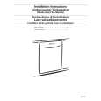
Removing Existing Worm Drive Handle (Fig.1)
C B
! WARNING The saw must be unplugged from power source before replacing the handle set. Contact
with live internal wiring or terminals will cause electric shock. 1. Make sure that your Worm Drive Saw is unplugged.
B
2. Remove the two bottom screws that attach the rear handle to the motor housing. These two screws are located at the bottom of the rear handle. A Please note that these screws are set with high torque and may be difficult to remove.
A
D
3. Remove the two top screws that attach the rear handle to the motor housing. These two screws are located at the top of the rear handles. B Please note that these screws are set with high torque and may be difficult to remove. 4. Remove all five screws that hold the rear handle together. These screws are located on side of the rear handle. C
11 2 2
5. Open the rear handle, exposing the inside components of the handle. Do this by lifting the top section of the handle at the seam line running down the center length of the handle. 6. Remove the screw connecting the green ground wire to the motor housing. D 7. Remove the screw that attaches the trigger to the Handle. E 8. Lift the trigger with attached wires away from the handle.
Motor Motor Moteur
Black Noir Negro
White Blanc Blanco Cord Cordon Cordón Green Vert Verde
9. Remove the two black wires that lead from the motor housing to the trigger assembly. Do this by removing the two scews that hold the wires into the trigger assembly. F 10. You will be left with the worm drive motor housing with two black wires coming from the rear of the motor housing. Please discard all other components from the removed worm drive handle.
FIG. 2
A E
Attaching New Worm Drive Direct Connect Handle (Fig. 2)
1. Remove Direct Connect Worm Drive Handle Set from packaging. All necessary screws are contained in the included screw bag.
B G
2. Open the Direct Connect Worm Drive Handle to expose the Trigger Assembly. 3. Attach the two black wires that run from motor Housing to the two open ports on the trigger assembly. A 4. Feed the two black wires through the wire slots located below the Trigger assembly. B 5. Attach the green ground wire from the direct connect handle to the ground port located on the motor housing. C
D
6. Feed the green wire through the wire slot located near the bottom right of the Direct Connect Worm Drive Handle. D
C
7. Make sure that the power receptacle E rests securely in the proper position. 8. Close handle together making sure that all wires are contained within the handle. 9. Insert and tighten 6 handle screws. G
FIG. 3
10. Insert and tighten 1 cord retention slot screw. H Proper cord routing for the handle see figure 3 and 4.
Installing Power Cord
© Robert Bosch Tool Corporation 1800 W. Central Road Mt. Prospect, IL 60056 -2230 Exportado por: Robert Bosch Tool Corporation Mt. Prospect, IL 60056 -2230, E.U.A. Importado en México por: Robert Bosch, S.A. de C.V., Calle Robert Bosch No. 405, Zona Industrial, Toluca, Edo. de México, C.P. 50070, Tel. (722) 2792300
DIRECT CORD CONNECT SYSTEM HAS BEEN CONFIGURED TO BE USED WITH 12AWG SJ CORD, MAXIMUM LENGTH OF 50 FEET. INSPECT THE CORD, DO NOT USE IF DAMAGED. 1. Loop cord as shown in figure 3.
! WARNING
2. Insert looped end of cord through slot in handle and loop cord into channel provided in handle as shown figure. 4).
FIG. 4
ATTENTION: before inserting plug into handle, always make sure you leave enough cord at plug end to avoid tension on plug when inserted into tool. 3. Push end of plug through spring clip and into female outlet in handle as shown below. 4 To remove plug from tool, simply remove from outlet and pull away from spring clip. NOTE: If the spring clip does not securely hold the plug it may be necessary to lightly squeeze the clip together with a pliers.
2 610 917 783 7/04
Printed in U.S.A.
|
|
|
> |
|