|
|
|
Categories
|
|
Information
|
|
Featured Product
|
|
|
 |
|
|
There are currently no product reviews.
 ;
Even if the PDF is a scan, I can read the information I need.
The price is affordable and the service (mail sending) is very fast.
Thanks ! Regards. William (Fan of Kenwood)
;
Very good quality original datasheet!I like this amazing website!!!!!!
 ;
Excellent just what I needed to replace the electrolytic caps and make this old gem a beauty again. Was as scan of the original photocopied service manual.
;
It was helpful to get schematic with waveforms in important points and lot of service information. Manual is good quality, fast delivered. Of course it is hardcopy of paper one with all its disadvantages.
;
I want to give you a real heads-up for your desire to enable such people as I to acquire the information I need to maintain the older types of equipment such as this Akai HXA351W. You do a swell job with all the processes you have to perform so I can have a legible, thus usable
document which does not send me crazy trying to figure out the blurry text of a bad copy.
Very well done, Thomas.
Touch current check
(After completing the work, measure touch current to prevent an electric shock.) �Plug the AC cord directly into the AC outlet. Do not use an isolation transformer for this check..
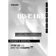
�Connect a measuring network for touch currents between each exposed metallic part on the set and a good earth ground such as a water pipe, as shown in Figure D.1
�The potential at any point(TOUCH CURRENT) expressed as voltage U1 and U2 does not exceed the following value:
The part or contact of a TERMINAL is not HAZARDOUS LIVE if: a) the open-circuit voltage does not exceed 35 V (peak) a.c or 60 V d.c., or,if a)is not met, b) the measurement of the TOUCH-CURRENT shall be carried out in accordance with IEC 60990, with the measuring network described in annex D of this standard. The TOUCH CURRENT expressed as voltages U1 and U2, does not exceed the following values: - for a.c.:U1= 35 V(peak)and U2=0.35 V (perk); - for d.c.:U1= 1,0 V, NOTE 5 -The limit values of U2=0.35 V (peak) for a.c. and U1=1.0 V for d.c. correspond, to the values 0,7mA (peak) a.c. and 2,0 mA 2,0mA d.c. The limit value U1= 35 V (peak) for a.c. corresponds to the value 70mA (peak) a.c. for frequencies greater than 100 kHz.
Annex D (normative) Measuring network for TOUCH CURRENTS
A
Test TERMINALS
Rs= 1 500Ω
Cs= 0.22uF 10kΩ
B
Rb = 500Ω
U1
0.022uF
V
U 2 (V)
IEC 802/96
Resistance values in ohms(Ω) V: Voltmeter or oscilloscope (r.m.s or peak reading) Input resistance: �1 MΩ Input capacitance: � 200 pF Frequency range: 15 Hz to 1 MHz and d.c. respectively NOTE-Appropriate measures should be taken to obtain the correct value in case of non-sinusoidal waveforms. The measuring instrument is calibrated by comparing the frequency factor of U2 with the solid line in figure F.2 of IEC 60990 at various frequencies. A calibration curve is constructed showing the deviation of U2 from the ideal curve as a function of frequency. TOUCH CURRENT=U2/500(peak value)
Fig.D.1
|
|
|
> |
|