|
|
|
Categories
|
|
Information
|
|
Featured Product
|
|
|
 |
|
|
There are currently no product reviews.
 ;
El producto satisface las necesidades del servicio t
;
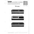
This is a good quality scan of the Operation & Maintenance (Service) Manual for the PAL version of this high-band broadcast umatic, BVU-800P
All schematics and lineup procedures appear to be included in this one manual AFAICT.
The file size is just over 113 MB which gives an idea of the quality and number of pages.
All of the schematics, which contain some fairly small print, are easily readable when you zoom into the page.
John Thompson, Newcastle Upon Tyne, England.
;
Good quality, all schematics of few of models. There is also short form of user manual and regulation manual.
;
Perfect copy of the service manual. you can enlarge every page, and it comes up
with all details.
;
It´s very very nice manual with all, what i need. Original in good quality. Very fast business. Very much thanks...
ENGLISH
1-3-3. E : 62 : 12 [Shift Lens Overheating (Yaw)] Occurred (SR7/SR7E/SR8/SR8E)
Connect by the SeusEX and perform the following process. Order Block Page Address Data 1 2 3 4 5 6 7 8 9 10 11 12 13 11 11 11 11 11 11 11 11 80 80 80 80 80 80 80 80 6BB2 7D47 7D49 7D49 7D47 7D49 7D49 6BB2 01 F0 01 00 10 01 00 00 Write the data. Write the data. Write the data. (Note 1) Write the data. Write the data. Write the data. (Note 1) Write the data. Write the data. Procedure
JAPANESE
Check if the shift lens moves while setting the order 2 to 7. If the shift lens does not move, replace the lens block (Note 2). When the shift lens moved, proceed to the order 10. While setting the order 2 to 7, measure with an oscilloscope the output voltage of R5737 in the periphery of IC5703 on the LD-228 board to check the output voltage varies. If the output voltage does not vary, replace the lens block (Note 2). When the output voltage varied, proceed to the order 12. Turn the power OFF. While measuring with an oscilloscope the output voltage of R5792 in the periphery of IC5703 on the LD-228 board, turn the power ON to check that the output voltage immediately after the power on change as shown in Fig. 2. If the output voltage change as shown in Fig. 2, replace the lens block (Note 2). If it does not change as shown in Fig. 2, inspect the camera control circuit (IC1803 of VC-504 board) periphery.
14
Note 1: Finish this operation within 10 seconds. If it is likely to take more than 10 seconds, set block: 11, page: 80, address: 7D49, data: 00, and then retry. Note 2: When the lens block was replaced, execute the necessary adjustment items referring to Service Manual, ADJ. After the adjustment, make sure with the STEADYSHOT turned ON that the steadyshot functions appropriately in the handheld operation.
1-3-4. E : 62 : 20 [Abnormality of Thermistor] Occurred (SR7/SR7E/SR8/SR8E)
Order 1 2 3 Turn the power ON. Check that R1846 in the periphery of IC1803 on the VC-504 board is 0 � and energizes. If it is not energizes, replace the R1846. When R1846 is 0 � and energizes, replace the lens block (Note). Check that no error occurs, after replacing the lens block and performing the necessary adjustment. If an error occurs, inspect the camera control circuit (IC1803 of VC-504 board) periphery. Procedure
Note: When the lens block was replaced, execute the necessary adjustment items referring to Service Manual, ADJ. After the adjustment, make sure with the STEADYSHOT turned ON that the steadyshot functions appropriately in the handheld operation.
HDR-SR5/SR5C/SR5E/SR7/SR7E/SR8/SR8E_L2 1-5
|
|
|
> |
|