|
|
|
Categories
|
|
Information
|
|
Featured Product
|
|
|
 |
|
|
There are currently no product reviews.
 ;
Perfect quality. Was able to fix speed drifting on my Sansui Turntable using the service manual instructions for PLL adjustment.
;
I am very happy regarding the online purchase of this manual from Owner-Manuals.com as with this I could set right my Denon CD player and Amplifier.
I once again sincerely thank them for the prompt service which was rendered to me.
N. Shanker
;
More than pleased with my prurchase, very good product for the price.
;
Manual-link came 30 minutes after having paid for an extremely rare (40 years old) item (sony icr-120) and helped me to get the radio rework again. So really good help for me, fast and reliable delivery and -taken that into consideration- a very reasonable price for that service. So thanks again! Mike, Germany
 ;
Some of the pictures in this manual are a bit irritating. I had to dissassemble the unit and some of the screws have different threads, which is not mentioned in this manual. Also some of the drawings of the boards look different than the actual boards.
After all, the manual was very useful. I was able to recalibrate the capstan drive and it is working fine again.
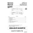
n 1-27. ITC (Integrated Tube Component) adjustments
The following ITC adjustments should be made only when a new picture tube is installed, or convergence is poor. All set-up adjustments above-mentioned must be completed before any further ITC adjustment is attempted. Receive an entire white raster signal and turn ON the Power Switch. Perform adjustment after a warm-up of at least an hour. Perform the following adjustments by setting H-convergence and V-convergence to center indication. Notes: See Chapter 5 concerning parts list for the ITC adjustments.
* PURITY MAGNET should not be turned during the ITC adjustments.
< Top view >
XV
< Side view >
PURITY MAGNET* 4-POLE MAGNET 6-POLE MAGNET
YV(a)
+
Yh(t)
+
TRD XV
+
DEFLECTION YOKE
ê
CRT face
DIFFERENTIAL COIL
SEPARATOR
LOCKING RING BOW MAGNET
1-27-1. LANDING correction
Landing meter setting: l Mode Select Switch: Monitor Normal Note: Mode Select Switch should be set before turning on the power switch of the landing meter. l Volt: 2V l Time: 50ms l Gain: 7 l Unit: % for LND-070, 0.8µm (1%=0.8µm) for LND-072 1) Face the CRT screen to east and set it vertically. 2) Degauss the entire screen with degausser. è See "EXTERNAL DEGAUSS". 3) Select DEGAUSS and press the MENU Button. 4) Receive an entire green signal. 5) Adjust the horizontal size to make it full-scan. 6) Apply the landing meter to TL (top-left), TR (top-right), BL (bottom-left) and BR (bottom-right) in the right hand side figure. 7) Confirm that "H" reading of the landing meter is within ±20% at each point. 8) Adjust rrc with the front buttons so that the "H" reading difference between T (top) and B (bottom) in the right hand side figure is as follows: | T-B | = ±3%. 9) Adjust Bottom-right, Top-right, Top-left and Bottom-left respectively with the front buttons so that "H" reading of the landing meter at each point is as follows: TL: �8 to �2% TR: +2 to +8% BL/BR: �3 to +3% - 13 20mm
TL
T B
TR
20mm
BL
BR
|
|
|
> |
|