|
|
|
Categories
|
|
Information
|
|
Featured Product
|
|
|
 |
|
|
There are currently no product reviews.
 ;
Ottima qualità grafica e completo nelle notizie. Costo abbastanza contenuto.
;
Great and quick support. The maual was exactly what I was looking for and my problem
solved. Many thanks.
;
Very good service Within one day i received a pdf of the users manual and electric circuits so I was able to measure the different voltages in the printed circuit and find out the fault Payment was also reliable and easy.Without the manual i could not have repaired.So thanks to "Search for a manual"
 ;
you are doing great job guys.....my father ask me to find out the schematics of Sony KV25R1D to sort out the problem ..(he was electrical technician, and excperianced with TV and simillar stuff). finally he found the cause and change all necessary parts....now he has got working old dog..and is very happy!!... thank you all.. NB..he also saved the repair cost.
;
Perfect. Received my manual within 24 hours. Clear scan of the manual I needed. No problem.
3.4
SYSCON CIRCUIT
Note: � When perform this adjustment, remove the Mechanism assembly. 3.4.1 Timer clock
Signal Mode Equipment (A) (B) (C) � No signal � EE � Frequency counter [HR-J271MS/J471MS] � IC3001 pin 29 � IC3001 pin 57 � C3015 + and � [HR-J677MS/J777MS] � IC3001 pin 61 � IC3001 pin 24 � C3026 + and �
Measuring point (D1) (D2) (D3) Measuring point (D1) Short point (D2) (D3) Adjustment part (F)
----------------------------------
[HR-J271MS/J471MS] � C3018 (TIMER CLOCK) [HR-J677MS/J777MS] � C3025 (TIMER CLOCK) � 1024.008 ± 0.001 Hz (976.5549 ± 0.0010 µsec)
Specified value
(G)
[HR-J271MS/J471MS] (1) Connect the frequency counter to the measuring point (D1). (2) Connect the short wire between the short point (D2) and GND. (3) Short the leads of capacitor (D3) once in order to reset the microprocessor of the SYSCON. (4) Adjust the Adjustment part (F) so that the output frequency becomes the specified value (G). [HR-J677MS/J777MS] (1) Connect the frequency counter to the measuring point (D1). (2) Connect the short wire between the short point (D2) and Vcc (5V). (3) Short the leads of capacitor (D3) once in order to reset the microprocessor of the SYSCON. (4) Disconnect the short wire between the short point (D2) and Vcc then connect it again. (5) Adjust the Adjustment part (F) so that the output frequency becomes the specified value (G).
3-3
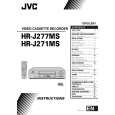 $4.99 HRJ271MS JVC
Owner's Manual Complete owner's manual in digital format. The manual will be available for download as PDF file aft…
|
|
|
> |
|