|
|
|
Categories
|
|
Information
|
|
Featured Product
|
|
|
 |
|
|
There are currently no product reviews.
 ;
Well.. I'd searched for this manual and although I found many copies online I was pleased to find your website with a well balanced pricing system and easy to search and follow links. That together with the very quick response time was just what I was looking for.. being a very impatient tech.. ;-) I had the service manual in front of me within a short time.
Bookmarked.. and you can bet I will always come here first for my service & user manuals..
best regards
Ed(Tony) Foley
G7WHK
;
I will definitely be back for more information when I need it.
;
The service manual when downloaded and printed out was clear and easy to read. I would have liked to have been able to enlarge some details, but this was not possible as the file permissions did not allow this. The service was very good. The time taken from placing my order to downloading the document was only a few minutes.
 ;
The manual is useful for trouble shooting for an old instrument. It saved money,and let me enjoy DIY.
;
Perfect source of information for replacing the HDD and performing general diagnostics.
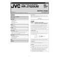
4.2 Mechanism compatibility adjustment Note: � Although compatibility adjustment is very important, it is not necessary to perform this as part of the normal servicing work. It will be required when you have replaced the A/C head, drum assembly or any part of the tape transport system. � To prevent damaging the alignment tape in the compatibility adjustment, prepare a cassette tape (for self-recording/playback), perform a test on it by transporting it and making sure that the tape is not bent by the tape transport mechanisms such as in the guide rollers.(See Fig.4-2b.) 4.2.1 Tension pole position Note: � This adjustment must be performed every time the tension band is replaced.
Signal Mode (A) � Back tension cassette gauge [PUJ48076-2] (B1) � PB (B2) � Eject end � Adjust pin [Mechansim assembly]
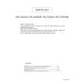
4.2.2 FM waveform linearity
Signal (A1) � Alignment tape(SP, stairstep, PAL) [MHPE] (A2) � Alignment tape(LP, stairstep, PAL) [MHPE-L] (UA Model) (A1) � Alignment tape(SP, stairstep, PAL) [MHP] (A2) � Alignment tape(EP, stairstep, PAL) [MHP-L] (UB, UM Model) (B) � PB (C) � Oscilloscope (D) � TP106 (PB. FM) (E) � TP111 (D. FF) (F) � Guide roller [Mechanism assembly] (G) � Flat V. PB FM waveform (H) � Roller driver [PTU94002]
Mode Equipment Measuring point External trigger Adjustment part Specified value Adjustment tool
(1) Play back the alignment tape (A1). (2) Apply the external trigger signal to D.FF (E), to observe the V.PB FM waveform at the measuring point (D). (3) Set the VCR to the manual tracking mode. (4) Make sure that there is no significant level drop of the V.PB FM waveform caused by the tracking operation, with its generally parallel and linear variation ensured. Perform the following adjustments when required. (See Fig. 4-2c.) (5) Reduce the V.PB FM waveform by the tracking operation. If a drop in level is found on the left side, turn the guide roller of the pole base assembly (supply side) with the roller driver to make the V.PB FM waveform linear. If a drop in level is on the right side, likewise turn the guide roller of the pole base assembly (take-up side) with the roller driver to make it linear. (See Fig. 4-2c.) (6) Make sure that the V.PB FM waveform varies in parallel and linearly with the tracking operation again. When required, perform fine-adjustment of the guide roller of the pole base assembly (supply or take-up side). (7) Unload the cassette tape once, play back the alignment tape (A1) again and confirm the V.PB FM waveform. (8) After adjustment, confirm that the tape wrinkling does not occur at the roller upper or lower limits. (See Fig. 4-2b.) [Perform adjustment step (9) only for the models equipped with SP mode and EP (or LP) mode.] [Perform adjustment step (9) only for the models equipped with SP mode and EP (or LP) mode.] (9) Repeat steps (1) to (8) by using the alignment tape (A2).
Improper Proper
Adjustment part (F) Specified value (G)
� 25 - 51 gf·cm (2.45 - 5 x 10⁻³ Nm)
(1) Play back the back tension cassette gauge (A). (2) Check that the indicated value on the left side gauge is within the specified value (G). (3) If the indicated value is not within the specified value (G), perform the adjustment in a following procedure.(See Fig.4-2a.) a) Remove the top frame, cassette holder and side frames (L/R) all together. (Refer to the SERVICE MANUAL No.86700 [MECHANISM ASSEMBLY].) b) Rotate the loading motor gear to move the control plate so that the triangular stamping to the left of the "P"stamping is aligned with the stamping (a) on the main deck. This positioning is mode (B1). c) Adjust by turning the adjustment pin so that the tip of the tension arm is aligned with the stamping (b) on the main deck. d) Rotate the reel disk (S) by about one turn clockwise and make sure that the round hole of the adjustment pin is located in the "OK" range. If it is outside this range, restart the adjustment from the beginning. After completion of the adjustment, rotate the loading gear motor to return it to the mode (B2) position.
TENSION ARM
(a) GUIDE ROLLER
CONTROL PLATE Stamping(a)
Stamping(b) OK
(b) GUIDE POLE
Fig.4-2b
NG
ADJUST PIN
Fig.4-2a
(No.YD007)1-11
|
|
|
> |
|