|
|
|
Categories
|
|
Information
|
|
Featured Product
|
|
|
 |
|
|
There are currently no product reviews.
 ;
Even if the PDF is a scan, I can read the information I need.
The price is affordable and the service (mail sending) is very fast.
Thanks ! Regards. William (Fan of Kenwood)
;
Very good quality original datasheet!I like this amazing website!!!!!!
 ;
Excellent just what I needed to replace the electrolytic caps and make this old gem a beauty again. Was as scan of the original photocopied service manual.
;
It was helpful to get schematic with waveforms in important points and lot of service information. Manual is good quality, fast delivered. Of course it is hardcopy of paper one with all its disadvantages.
;
I want to give you a real heads-up for your desire to enable such people as I to acquire the information I need to maintain the older types of equipment such as this Akai HXA351W. You do a swell job with all the processes you have to perform so I can have a legible, thus usable
document which does not send me crazy trying to figure out the blurry text of a bad copy.
Very well done, Thomas.
3.1.6 Manual tracking mode (Auto tracking ON/OFF) setting (1) In order to set to the manual tracking mode during tape playback, press the �SP/EP(LP)� button on the remote control unit. � Each press of the button switches the auto tracking ON or OFF. � When the auto tracking is OFF, the monitor screen displays �AT: OFF�. � When the manual tracking mode is set, the tracking is placed at the center position. (2) Press �channel +/-� to adjust the tracking manually.
3.2 Mechanism compatibility adjustment Notes: � Although compatibility adjustment is very important, it is not necessary to perform this as part of the normal servicing work. It will be required when you have replaced the A/C head, drum assembly or any part of the tape transport system. � To prevent damaging the alignment tape in the compatibility adjustment, prepare a cassette tape (for self-recording/playback), perform a test on it by transporting it and making sure that the tape is not bent by the tape transport mechanisms such as in the guide rollers.(See Fig.3-2-2a.) 3.2.1 Tension pole position Notes: � This adjustment must be performed every time the tension band is replaced.
Signal Mode Adjustment part Specified value (A) (B1) (B2) (F) (G)
� Back tension cassette gauge
[PUJ48076-2]
� PB � Eject end � Adjust pin [Mechansim assembly] � 25 - 51 gf�cm (2.45 � 5 � 10-3 Nm)
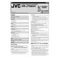
(1) Play back the back tension cassette gauge (A). (2) Check that the indicated value on the left side gauge is within the specified value (G). (3) If the indicated value is not within the specified value (G), perform the adjustment in a following procedure.(See Fig.3-2-1a.) 1) Remove the top frame, cassette holder and side frames (L/R) all together. (See �section 2 mecha-nism�.) 2) Rotate the loading motor gear to move the control plate so that the triangular stamping to the left of the �P� stamping is aligned with the stamping (a) on the main deck. This positioning is mode (B1). 3) Adjust by turning the adjustment pin so that the tip of the tension arm is aligned with the stamping (b) on the main deck. 4) Rotate the reel disk (S) by about one turn clockwise and make sure that the round hole of the adjustment pin is located in the �OK� range. If it is outside this range, restart the adjustment from the beginning. After completion of the adjustment, rotate the loading gear motor to return it to the mode (B2) position.
TENSION ARM
CONTROL PLATE Stamping(a) Stamping(b) OK
NG ADJUST PIN
Fig. 3-2-1a
3-2
|
|
|
> |
|