|
|
|
Categories
|
|
Information
|
|
Featured Product
|
|
|
 |
|
|
There are currently no product reviews.
 ;
This was a hard to find manual. When I did find it , some sites wanted way too much for the file.
Owner-manual .com had it for a really reasonable price. Not only that but it was sent very quickly and was a quality scanned document, unlike some others I purchased from a different site.
Good job guys!!
Larry
;
Fast and courteous service. Product delivered as described. Thank you.
;
Last week I bought a second hand Panasonic AG-7500 SVHS Hi-Fi Video Cassette Recorder. It is a professional machine with many video and audio options. I feared it would be a huge quest to find a manual. I was delighted when I found owner-manuals.com. After payment I received the file to download the next day already. The quality is great. I am very happy. Thanks!
;
The owner's manual/operating instructions that I purchased was the original factory document and it was in at least three and maybe more languages. I no longer have it because I sold the tape recorder and included the owner's manual/operating instructions and a service/repair manual that I bought on ebay for the new owner.
;
This manual is very useful. Because pioneer sx-q180 is unhandy to use without manual.
UX-A60V
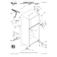
Removing the TRAMECHA Assembly (Refer to Figs. 6 to 9.)
Remove the CL. base assembly and tray. Reference: The TRAMECHA assembly can be removed without removal of the mechanism board. 1. If the TRAMECHA assembly is lowered and it is TRAMECHA located out of the PLAY position, turn the idle gear assembly in the arrow-marked direction so that the hole in the part f of the tray gear meets the hole on the CL. base assembly. (Set the TRAMECHA assembly at the PLAY position.) 2. Remove the three screws B fastening the TRAMECHA assembly and then remove the TRAMECHA assembly upwards from the front side.
3. At the same time, remove the spring from the groove of the CH. base assembly in the part g of the TRAMECHA assembly. Part g Idle gear
B
B
Tray gear
B
Fig. 6
Tray gear
Note: When reinstalling the TRAMECHA assembly: Check to see if the spring is properly engaged with groove of the CH. base assembly in the part g of the TRAMECHA assembly. After making sure that the three insulators of the TRAMECHA assembly are properly set on the bosses of the L. base assembly's guide, fasten them with the screws.
Part f
L. base assembly
Fig. 7
Spring Part g
Fig. 8
Spring
Groove of CH. base assembly
Fig. 9
1-18
|
|
|
> |
|