|
|
|
Categories
|
|
Information
|
|
Featured Product
|
|
|
 |
|
|
There are currently no product reviews.
 ;
Great Job even clear than the one before!!!! god organization- I'm always very satisfied
;
I'm very happy that you all are performing an incredible good job. Furthermore what you did is very useful for all people as me that have electronics as an hobby.Thank you!!!!!
;
Manual found fast and good quality, very helpfull service
;
8-17-12 Been using the sight for about 6 months. Fast Downloads and top quality
Manuels !
 ;
Everything was great, the manual, the response time, the simplicity of the order, and the
Price. The only thing that I could possible say on a negative note would be that the manual I ordered was more for a service tech. There were a lot of schematic diagrams that didn't help me solve the problem. However I would order again and recommend the web sight to others.
2.2 Replacement of the main mechanism parts 2.2.1 Cassette holder 2.2.1.1 Removal (1) Remove the screws (a) and (b). (2) Hold up the top frame, cassette holder assembly, drive arm assembly and side frames (L/R) all together and remove them by releasing the hooks (a) and (b).
Screw (a)
2.2.1.3 Disassembling (1) Release hook (a) to remove the earth spring (1) from the top frame. (2) Release the catches (a) and (b) and pull the top frame in the direction shown by the arrow (a) to remove it. (3) Pull out the side frame (R). (4) Pull out the cassette holder assembly and drive arm assembly from the side frame (L).
Hook (a)
Catch (a)
Catch (b)
Screw (b)
Hook (a) Hook (b)
EARTH SPRING(1) Arrow (a) TOP FRAME
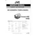
Fig. 2-2-1a 2.2.1.2 Installation (phase adjustment) (1) Turn gear (a) of the loading motor assembly so that the main deck connects to the guide hole (a) of the drive lever. (2) Hook the main deck to hooks (a) and (b). (3) Place the projection of the drive lever to section (a) of the side frame (R) and install the cassette holder to the main deck. Make sure that the bosses of the side frame (L/R) connect with the holes (a) and (b) of the main deck. (4) Secure screws (a) and (b).
Screw (a) Screw (b)
SIDE FRAME(L) CASSETTE HOLDER Assembly DRIVE ARM Assembly
SIDE FRAME(R)
Fig. 2-2-1c 2.2.1.4 Assembling (installation and phase adjustment) (1) Turn gear (a) of the loading motor assembly so that the main (2) (3) (4) deck connects to the guide hole (a) of the drive lever. Place the projection of the drive lever on section (a) of the side frame (R) and install the side frame (R) to the main deck. Secure screw (b). Place section (b) of the drive arm on the gear of the side frame (R). Make sure that the pin of the door opener connects with section (c) of the drive arm. Place the drive arm on section (d) of the side frame (L) and install the side frame (L) on the main deck. Be sure to con-
Hook (a) Hook (b) Section (a)
(5)
Hole (b) Hole (a) Guide hole (a) DRIVE LEVER Gear (a)
nect the earth spring (1) to the side frame (L). (6) Secure screw (a). (7) Turn gear (a) of the loading motor assembly until the drive arm is vertical. (8) Place the slit of the side frame (L/R) at the foot of the cassette holder assembly and install the cassette holder. (9) Place the top frame on the position guide (a) of the side frame (L/R) and push it in the direction shown by the arrow (a) for installation. (10) Hook the earth spring (1) to the hook (a) of the top frame.
Fig. 2-2-1b 2-4
|
|
|
> |
|