|
|
|
Categories
|
|
Information
|
|
Featured Product
|
|
|
 |
|
|
There are currently no product reviews.
 ;
The service manual is as described and received the link to the download sooner than expected. Great service, quality product. This site is a big help in the electronics repair business.
;
Il service manual molto accurato. Rapidi nella risposta
;
Quick site processing. A complete and very useful manual with all details. Thank you!
;
Quick service response. A useful and very rare service manual with all details. I recomend this service.
;
I ordered this manual sometime in the afternoon and I received it on my e-mail the same evening.
This is a fantastically good and properly scanned copy of the original manual. All pages are of the same scale and they overlap each other. It means that you can print the manual and easily make it as a convenient paper manual.
The content of the manual is fantastic. Alignment descriptions, PCB layouts and elementary diagrams are explicit and precise. I immediately found what I was looking for. Thanks to this manual and Owner-Manuals.com my amplifier is alive again. Many thanx indded!
5.2
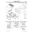
FINAL ASSEMBLY <M2>
BEWARE OF BOGUS PARTS Parts that do not meet specifications may cause trouble in regard to safety and performance. We recommend that genuine JVC parts be used. 516
1
505
NOTE) INERTIA PLATE should be attached so as to ser small diameter of central round hole above.
515
g
520
522 521
503
502
d
519A 515 519
e
a
d
MECHANISM ASSY<M4> 516
g
533
c
510
510
NOTE) When attaching ROLLER ARM ASS'Y, attach the hook(L3c) before the spring(P3a). NOTE) After attached ROLLER ARM ASS'Y, tighten screw(S3g) with slit washer(W3a).
503 MAIN BOARD ASSY<03>
532
Q 30 03
510
517
g
Insert the bushing of POWER CORD so as not to twist the cord.
533
b c'
D 30 01
dc e
JS3001
REAR SIDE
504
533
CN5 00 1
1 00 JS 3
00 Q3
2
a
d'
c' b
b h
<Phase alignment> Accord the position of V gap on R. Encoder and PWB silk " ". Accord the position of Boss on R. Encoder and PWB silk " ".
511
k h a f g d' c' b f b c'
523
e
For the prevention of the DRUM FPC damage. When you attach the MECHA UNIT on B. CHASSIS. Attach the MECHA UNIT after the positioning boss "z" of the B. CHASSIS is matched to the positioning hole of the MECHA UNIT.
"Z"
To main CN7001
b
501
501A
f
BACK SIDE
WR4
ADV. JOG BOARD ASSY<38>
Front panel back side
f
501B
CN7003
f
f
530
ONLY USED FOR HR-S6955EK
534
512
f
f
529 [HR-S6955EK]
From CAPSTAN MDA Right side
Right side
NOTE
1. Insert direction of FCC WIRE as follows. Right side Back side
electrode side
1
supporting side
CN5001 CN2001
2. FFC WIRE and DRUM FPC WIRE should be insert as follows. OK NG 90
DRUM
CN501
CN
CN
CN
A/C HEAD
3. Insert direction of POWER CORD.
U/U(C)/JPN WHITE LINE
CN7102
Except U/U(C)/JPN BLUE
CN7105
NEUTRAL
NEUTRAL
CN5001
CN5001
CN7001
ONLY USED FOR HR-S6955EK
from FRONT PANEL Right side For JOG
5-2
|
|
|
> |
|