|
|
|
Categories
|
|
Information
|
|
Featured Product
|
|
|
 |
|
|
There are currently no product reviews.
 ;
Good service, well organized. Cheap, and the service manual was as expected. A valuable service for those of us wanting to keep the old junk going!
;
The manual arrived very quickly and had all the information I needed - Very satisfied with this seller. - Thanks -
;
Good quality, the manual help me to repair the echo/reverb section
;
A good service manual with lots of info and a very fair price
;
Great value, good scan, just as expected, everything that you need.
2.4 Service position This unit has been designed so that the Mechanism and Main board assemblies can be removed together from the chassis assembly. Before diagnosing or servicing the circuit boards, take out the major parts from the chassis assembly. 2.4.1 How to set the �Service position� (1) Refer to the disassembly procedure and perform the disassembly of the major parts before removing the Mechanism assembly. (2) Remove the screws that fix the Mechanism assembly to the Chassis assembly. If any other screws are used to fix the boards, remove them also. (3) Remove the combined Mechanism and Main board assemblies. (4) If any other major parts are used, remove them also. (5) Connect the wires and connectors of the major parts that have been removed in steps (1) to (4). (Refer to Fig. 2-41a.) (6) Place the combined Mechanism, Main board and other board assemblies upside down. (7) Insert the power cord plug into the power outlet and then proceed with the diagnostics and servicing of the board assembly. Notes: � Before inserting the power cord plug into the power outlet, make sure that none of the electrical parts are able to short-circuit between the workbench and the board assembly. � For the disassembly procedure of the major parts and details of the precautions to be taken, see �2.2 Removing the major parts�. � If there are wire connections from the Main board and Mechanism assemblies to the other major parts, be sure to remove them (including wires connected to the major parts) first before performing step (2). � When carrying out diagnosis and repair of the Main board assembly in the �Service position�, be sure to ground both the Main board and Mechanism assemblies. If they are improperly grounded, there may be noise on the playback picture or FDP counter display may move even when the mechanism is kept in an inoperative status. � In order to diagnose the playback or recording of the cassette tape, set the Mechanism assembly to the required mode before placing it upside down. If the mechanism mode is changed (including ejection) while it is in an upside down position the tape inside may be damaged. � For some models, the mechanism and board assemblies are attached by connectors only. When carrying out a diagnosis or repair of the boards in the �Service position�, make sure that the connectors are not disconnected. 2.5 Jig RCU mode This unit uses the following two modes for receiving remote control codes. (1) User RCU mode:Ordinary mode for use by the user. (2) Jig RCU mode: Mode for use in production and servicing. When using the Jig RCU, it is required to set the VCR to the Jig RCU mode (the mode in which codes from the Jig RCU can be received). As both of the above two modes are stored in the EEPROM, it is required to set the VCR back to the User RCU mode each time that an adjustment is made or to check that the necessary operations have been completed.These modes can be set by the operations described below. Note: � Confirm the RCU mode when exchanged parts. Since some SERVICE PARTS sets the VCR to the Jig RCU mode as initial setting.
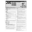
ONLY USED FOR HR-S5965EF CN1601 CN512
TP106 PB FM
TP111 D.FF
TP2254 A.REC.FM
TP2253 A.PB.FM
TP4001 CTL.P
Main board assembly
VR1603 BURST
VR1601 R-Y VR1602 B-Y
CP4002 CP3002
S/P converter board assembly
SECAM board assembly
C3025 Timer clock TP GND TP7001 TEST
Fig.2-4-1a
User RCU mode
S-VHS
Jig RCU mode
S-VHS
( not displayed)
Fig.2-5-1a User/Jig RCU mode 2.5.1 Setting the Jig RCU mode (1) Unplug the power cord plug from the power outlet. (2) Press and hold the �REC� and �PAUSE� buttons on the VCR simultaneously, while plugging the power cord plug into the power outlet. When the VCR is set to the Jig RCU mode, the symbols ( � : � ) in the time display of the FDP are turned off. (Refer to Fig.2-5-1a)
(No.82961)1-13
|
|
|
> |
|