|
|
|
Categories
|
|
Information
|
|
Featured Product
|
|
|
 |
|
|
There are currently no product reviews.
 ;
Good quality, all schematics of few of models. There is also short form of user manual and regulation manual.
;
Perfect copy of the service manual. you can enlarge every page, and it comes up
with all details.
;
It´s very very nice manual with all, what i need. Original in good quality. Very fast business. Very much thanks...
;
Purchased the manual that I was looking for at a great price and could download it easily.. Great service experience and for future purchases I plan to use the site.
Thank you very much
;
Exactly what was needed to assess the product - excellent value and great service
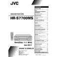
2.2.10 Rotary Encoder 1. How to remove (1) Remove the screw (A) and remove the rotary encoder by pulling it up. (See Fig. 2-2-10a.)
Rotary encoder (Front side) Screw(A) Guide marks
2.2.12 Change Lever Assembly, Direct Gear, Clutch Gear and Coupling Gear 1. How to remove (1) Release the two lugs of the rotary encoder guide in the arrow-indicated direction and remove the change lever assembly. (2) Remove the slit washer retaining the direct gear and remove the latter. Take care so as not to lose the washer and spring. (See Fig.2-2-12a.)
Change lever assembly Slit washer
Rotary encoder (Back side) Positioning pin of the rotary encoder
Washer ( 1) Spacer Direct gear Spring(A) Position the projecting side down. Spring(B) Spring (C) Spacer ( 1) Coupling gear ( 2) Clutch gear
*
Fig. 2-2-10a
*
*
Mark E
Lugs
Shaft of the rotary encoder guide
Control plate
Note: � The parts with marked ( ) have different types of mechanisms (standard type or highspeed FF/REW type).
*
Fig. 2-2-10b 2. How to install (Phase matching) (1) Make sure that the mark E of the control plate is in alignment with the mark of the loading arm gear shaft and bring the guide marks on the rotary encoder into alignment as indicated in Fig.2-2-10a. (See Fig. 2-2-10a and Fig. 2-2-10b.) (2) Turn over the rotary encoder with its guide marks kept in alignment and install it by fitting on the shaft of the rotary encoder guide and the positioning pin. (3) Tighten the screw (A) to complete the installation. 2.2.11 Clutch Unit (1) Remove the belt wound around the capstan motor and the clutch unit. (2) Remove the slit washer and remove the clutch unit.
*1 *2
: Uses the standard type mechanism only. : Uses the high-speed FF/REW type mechanism only.
Fig. 2-2-12a 2. How to install (1) Install the clutch gear, spring (A), spring (C), direct gear, spacer and others to the individual shafts of the main deck, and finally the slit washer. (See Fig.2-2-12a.) (2) Let the spring (B) drops into the rotary encoder guide hole and install the change lever assembly.(Take care not to mistake a direction of the spring.) The point is to slightly lift the clutch gear and catch it from the both sides with the assembly. (See Fig.2-2-12b.)
Rotary encoder guide Change lever assembly Spring(B) Clutch gear
Belt
Slit washer Clutch unit
Main deck
Main deck
Fig. 2-2-12b
Fig. 2-2-11a
2-10
|
|
|
> |
|