|
|
|
Categories
|
|
Information
|
|
Featured Product
|
|
|
 |
|
|
There are currently no product reviews.
 ;
A very well written and easy to understand manual.
;
There was no problem at all.After paying i had to wait only a few hours,than i could
download the manual in best pdf-quality.
Thank You !
 ;
I found this service manual to be complete in every detail except for troubleshooting charts. It would be helpful if it had a set of troubleshooting charts; however it is a very good manual otherwise and for the price it is very well worth it.
;
Complete manual included schematics layouts and alignment procedure, clear to read and magnify, extremely pleased with manual and owner manual . com's service
;
perfect, i am very satisfait for the réception of the sansui r-5l service manual, thank you very much
3.5.8 Sub DET [HR-S6700KR]
Signal Mode Equipment Adjustment part Specified value Adjustment tool (A) (B) (C) (F) (G) (H) � RF signal (sound carrier: S2) � Tuner � EE � Audio level meter � IC1501 pin 26 � T1501 (SUB DET) � Minimum distortion � LPF (30 kHz), HPF (400 Hz)
3.6 SYSCON CIRCUIT Note: � When perform this adjustment, remove the Mechanism assembly. 3.6.1 Timer clock
Signal Mode Equipment (A) (B) (C) � No signal � EE � Frequency counter � IC3001 pin61 � IC3001 pin24 � C3026 + and � � C3025 (TIMER CLOCK) � 1024.008 ± 0.001 Hz (976.5549 ± 0.0010 µsec)
Measuring point (D)
(1) Set the sound carrier of the RF signal generator to S2. (2) Connect the adjustment tool (H) to the measuring point (D). Then connect the equipment (C) to the adjustment tool (H). (3) Adjust the Adjustment part (F) so that the distortion level of the measuring point (D) becomes the specified value (G). 3.5.9 Pilot VCO [HR-S6700KR]
Signal Mode Equipment (A) (B) (C) � No signal � Tuner � EE � Frequency counter � IC1501 pin 11 � C1510 (+) terminal � C1510 (�) terminal � VR1502 (PILOT VCO) � 210 ± 5 Hz
Measuring point (D1) Short point (D2) (D3) Adjustment part (F) Specified value (G)
Measuring point (D1) Short point (D2) (D3) Adjustment part Specified value (F) (G)
(1) Connect the frequency counter to the measuring point (D1). (2) Connect the short wire between the short point (D2) and Vcc (5V). (3) Short the leads of capacitor (D3) once in order to reset the microprocessor of the SYSCON. (4) Disconnect the short wire between the short point (D2) and Vcc then connect it again. (5) Adjust the Adjustment part (F) so that the output frequency becomes the specified value (G).
(1) Connect the short wire between the short points (D2) and (D3). (2) Connect the equipment (C) to the measuring point (D1). (3) Adjust the Adjustment part (F) so that the frequency of the measuring point (D1) becomes the specified value (G). (4) Disconnect the short wire between the short points (D2) and (D3). 3.5.10 Separation [HR-S6700KR]
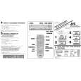
Signal Mode Equipment Adjustment part Specified value Adjustment tool (A) (B) (C) (F) (G) (H) � Sweep generator output (90 dB, 1 kHz) � EE � Oscilloscope � IC1501 pin 19 � VR1501 (SEPARATION) � Minimum level � Sweeper probe (See Fig. 3-5-10a.)
Measuring point (D)
Shorter than 8 cm
Shield
C : 1000 P R : 75� Earth
Out
Shorter than 5 cm
Fig. 3-5-10a
Sweeper probe
(1) Use the adjustment tool (H), supply 1 kHz R-only modulated IF signal to IF terminal of U/V tuner (front end). (2) Connect the equipment (C) to the measuring point (D). (3) Adjust the Adjustment part (F) so that the output level of the measuring point (D) becomes the specified value (G). 3-7
 $4.99 HR-S7800U JVC
Quick Start Quick start guide ( sometimes called quick guide ) contains most important information on how to use…
|
|
|
> |
|