|
|
|
Categories
|
|
Information
|
|
Featured Product
|
|
|
 |
|
|
There are currently no product reviews.
 ;
complete part-lists and pcb layout, schematic diagram is good enlargable,
;
Excellent, fast delivery, excellent product. Good luck!
;
This manual is for the usa model only. But it is clear
, accurate and comprehensive, including board layouts and schematics.
I found it extremely useful for my mitsubishi dp-86da, but the same diagram would also work for the realistic lab5000 and hi fi 80. Thanks.
;
Great to have extra resources for Service Manuals, Now days you can really not trouble shoot efficiently without one , Wayne at IRIONS TV & ELECTRONICS REPAIR Clearwater , Fl. 33755 727-446-7955
 ;
For five bucks you can barely buy a hamburger. Or for the same five bucks you can buy a service manual. Much more useful. (and better for your health, depending on where you buy your hamburgers).
Yes, there are free manual sites out there, but if they don't have what you want, you have to pay.
And five bucks isn't much. Not for full specs, schematics and adjustment and parts replacement procedures.
My only criticism is that grayscale illustrations aren't well rendered, but I've seen worse.
Schematics and text are clear.
I'll be happy to purchase from here again.
Mike
[email protected]
TABLE OF CONTENTS
HOW TO IDENTIFY MODELS .................................................................... 1 Circuit board assembly and unit compatibility between HR-XVC1U(or HR-XVC1UC) and HR-XVC1U/M(HR-XVC1UC/M) .. 1 DIFFERENT TABLE ................................................................................... 2 DISASSEMBLY INSTRUCTIONS 1. REMOVAL OF MECHANICAL PARTS AND P.C. BOARDS .......... 1-1 1-5. DECK CD AND DVD MT PCB ................................................. 1-1 SERVICE MODE LIST ....................................................................... 1-1 WHEN REPLACING EEPROM(MEMORY) IC .................................. 1-2 SERVO TIMING CHART ................................................................... 1-2 PREPARATION FOR SERVICING .................................................... 1-3 ELECTRICAL ADJUSTMENTS ........................................................ 1-3 2. ELECTRICAL ADJUSTMENT PARTS LOCATION GUIDE (Connector Connections) ......................................................... 1-4 2. CHARTS AND DIAGRAMS (2-1 to 2-41) INTERCONNECTION DIAGRAM ............................................ POWER SCHEMATIC DIAGRAM ............................................ MPEG SCHEMATIC DIAGRAM ............................................... MEMORY SCHEMATIC DIAGRAM ......................................... 2-1 2-3 2-5 2-7 SYSCON1 SCHEMATIC DIAGRAM ........................................ 2-9 DSP SCHEMATIC DIAGRAM ................................................. 2-11 MOTOR DRIVE SCHEMATIC DIAGRAM .............................. 2-13 READ CHANNEL SCHEMATIC DIAGRAM ........................... 2-15 AUDIO/VIDEO SCHEMATIC DIAGRAM ................................ 2-17 Y/C/AUDIO/CCD/HEAD AMP SCHEMATIC DIAGRAM ......... 2-19 VCR SYSCON SCHEMATIC DIAGRAM ................................ 2-21 TUNER/JACK SCHEMATIC DIAGRAM ................................. 2-23 REGULATOR SCHEMATIC DIAGRAM ................................. 2-25 DISPLAY SCHEMATIC DIAGRAM ......................................... 2-27 HI-FI/DEMODULATOR SCHEMATIC DIAGRAM ................... 2-29 DVD IN/OUT SCHEMATIC DIAGRAM ................................... 2-31 OPERATION SCHEMATIC DIAGRAM .................................. 2-33 PRINTED CIRCUIT BOARDS VCR ....................................... 2-35 PRINTED CIRCUIT BOARDS DVD ....................................... 3-39 PRINTED CIRCUIT BOARDS OPERATION .......................... 2-41 PRINTED CIRCUIT BOARDS POWER ................................. 2-41 3. PARTS LIST (3-1 to 3-7) 3.1 PACKING AND ACCESSORY ASSEMBLY <M1> ................... 3-1 3.2 ELECTRICAL PART LIST VCR BOARD ASSEMBLY<03> .................................................. 3-2 DVD BOARD ASSEMBLY<50> .................................................. 3-6
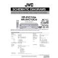
HOW TO IDENTIFY MODELS
How to recognize from the appearance of the model concerned is written below. Please distinguish from several contents currently printed on the rating label of the rear panel or �SPECIALIZER� logo mark of the front panel.
(blank) : HR-XVC1U or HR-XVC1UC /M : HR-XVC1U/M or HR-XVC1UC/M
"SPECIALIZER" logo mark 3D STEREO : HR-XVC1U or HR-XVC1UC N-2-2 : HR-XVC1U/M or HR-XVC1UC/M
RATING LABEL
Circuit board assembly and unit compatibility between HR-XVC1U (or HR-XVC1UC) and HR-XVC1U/M (or HR-XVC1UC/M)
Since the same parts are used for the VCR mechanism section and power supply circuit board assembly for the HR-XVC1U (or HRXVC1UC) and HR-XVC1U/M (or HR-XVC1UC/M), they are interchangeable. However, there is no compatibility for the VCR circuit board, DVD circuit board, and DVD drive unit. 1. The difference in the VCR circuit board is the connection cable that connects to the DVD circuit board. It is not possible to connect an old board to a new board. 2. The difference in the DVD circuit board is the substantial difference in external dimensions. There is also no compatibility in terms of specifications. <Reference> When an old VCR circuit board is forcibly connected to a new DVD circuit board, there is a terminal that changes HR-XVC1U (or HRXVC1UC): 3.3V�HR-XVC1U/M (or HR-XVC1UC/M): 9V and the DVD circuit board will be damaged. 3. It is possible to install the DVD drive unit in the chassis. However, since there is no compatibility between the DVD circuit board and the connection cable, it is not possible to connect old and new together. <Reference> If the entire set of revised parts is exchanged at once (DVD drive unit, VCR circuit board, DVD circuit board (with attachment angle)), the specifications for Spatializer will change from 3D Stereo � N-2-2. This type of process will cause non-compliance with certified specifications, so do not interchange old and new type parts. Compatibility Old/New Parts Compatibility Mechanical specifications (installation) Electrical specifications (connection) Yes No No No No � Yes Yes Yes Yes Yes Yes Software specifications � No � � No � 1
DVD drive unit DVD circuit board DVD circuit board attachment angle VCR mechanism unit VCR circuit board Power supply circuit board
|
|
|
> |
|