|
There are currently no product reviews.
 ;
I was very glad recieving the service manal from You. Manuals were delivered promptly and were correct as advertised. A complete and very usefull service manual with all details. Thank you!
;
Very clear copy. No pages missing. Big bonus is that it includes supplement. Price is affordable compared to what others ask for.
;
Found the quality of the copy excellent and a very quick service. I would certainly recommend the service.
;
Good quality, clear diagrams. Exactly what I needed.
 ;
Good product. All the information is invcluded, but due to the complexity of the amplifier, it still is difficult to get it to operation again.
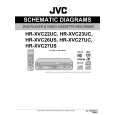
3.2.4 Removing the loading motor (See Figure 3-2k and Figure 3-2l) � Prior to the following procedure, remove the tray, the traverse mechanism assembly, and the elevator. (1) Remove the belt from the pulley. (2) Remove two screws C attaching the loading motor. (3) Remove two solders h on the switch board.
Belt Pulley C
Loading base Slide cam
Pulley C
Fig.3-2k
Switch board Part h
Loading motor
Fig.3-2l 3.3 Traverse mechanism assembly
3.3.1 Removing the pickup (See Figure 3-3a, Figure 3-3b) � Prior to the following procedure, remove the traverse mechanism assembly. (1) Remove one screw D attaching the plate. (2) Remove the plate and the leaf spring. (3) Lift i of the shaft 1, and pull out the shaft 1 from j. (4) Remove k of the pickup from the shaft 2. Attaching the pickup: (1) Engage k of the pickup to the shaft 2. (2) Insert the shaft 1 in j, and attach the shaft 1 to i. (3) Attach the leaf spring, and then attach the plate. Fix the leaf spring and the plate by using the screw D.
D Leaf spring Plate
Fig.3-3a
Shaft 2 Part j
Part k
Shaft 1 Part i
Fig.3-3b 1-14 (No.YD008)
|