|
|
|
Categories
|
|
Information
|
|
Featured Product
|
|
|
 |
|
|
There are currently no product reviews.
 ;
The service manual is as described and received the link to the download sooner than expected. Great service, quality product. This site is a big help in the electronics repair business.
;
Il service manual molto accurato. Rapidi nella risposta
;
Quick site processing. A complete and very useful manual with all details. Thank you!
;
Quick service response. A useful and very rare service manual with all details. I recomend this service.
;
I ordered this manual sometime in the afternoon and I received it on my e-mail the same evening.
This is a fantastically good and properly scanned copy of the original manual. All pages are of the same scale and they overlap each other. It means that you can print the manual and easily make it as a convenient paper manual.
The content of the manual is fantastic. Alignment descriptions, PCB layouts and elementary diagrams are explicit and precise. I immediately found what I was looking for. Thanks to this manual and Owner-Manuals.com my amplifier is alive again. Many thanx indded!
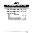
3.2.4 Removing the loading motor (See Figure 3-2k and Figure 3-2l) � Prior to the following procedure, remove the tray, the traverse mechanism assembly, and the elevator. (1) Remove the belt from the pulley. (2) Remove two screws C attaching the loading motor. (3) Remove two solders h on the switch board.
Belt Pulley C
Loading base Slide cam
Pulley C
Fig.3-2k
Switch board Part h
Loading motor
Fig.3-2l 3.3 Traverse mechanism assembly
3.3.1 Removing the pickup (See Figure 3-3a, Figure 3-3b) � Prior to the following procedure, remove the traverse mechanism assembly. (1) Remove one screw D attaching the plate. (2) Remove the plate and the leaf spring. (3) Lift i of the shaft 1, and pull out the shaft 1 from j. (4) Remove k of the pickup from the shaft 2. Attaching the pickup: (1) Engage k of the pickup to the shaft 2. (2) Insert the shaft 1 in j, and attach the shaft 1 to i. (3) Attach the leaf spring, and then attach the plate. Fix the leaf spring and the plate by using the screw D.
D Leaf spring Plate
Fig.3-3a
Shaft 2 Part j
Part k
Shaft 1 Part i
Fig.3-3b 1-14 (No.YD008)
|
|
|
> |
|