|
|
|
Categories
|
|
Information
|
|
Featured Product
|
|
|
 |
|
|
There are currently no product reviews.
 ;
as always, rapid and efficient, very good and clear prints
details clearly visible keep going this way!!!!!!
;
I expect a wonderful result as alaways!!!!!!
Usually is much faster....
;
Wow very wonderful and clear!!!! I will always trust them
;
Providing the manual works fine, quickly and without any problems for an acceptable price. After printing the service manual it took me only a short time to repair my carradio from Clarion. Thank You! Greetings from Heiko
;
I was searching a way to modify the original phono-in entry (for connection of vynil disc player, with RIAA equalization) to a line-in entry (for connection of modern analog entries, eg. ipod, mp3player).
This service manual gave me the correct hints.
It contains very useful infos for repairing and modifing the hi-fi, such as disassembling instructions, block diagrams, schematic diagrams, PCB prints, replacement parts list.
Very good!
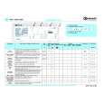
ADJUSTMENT
A MAIN C.B
MECHANICAL EXPLODED VIEW 1 / 1
2
SFR 2
* P HEAD
VOLUME
VR1
*
3 FWD
TP1 (L-CH)
SFR 1
*
4ZM-2 P7NC
TP2 (R-CH)
A
*
C
B
PHONES
SFR 51
J1
1
Note :
4
1
2
2
* : On the other soldering pattern side.
1. Tape Speed Adjustment Settings : � Test tape : When the tape starts running smooth, this adjustment is not necessary. If wow is conspicuous at the beginning of the tape-run, perform this adjustment following the procedures below. 1) Solder resistor pattern (A) of the MOTOR AND GOVERNOR MATCHING ADJ. resistor group. 2) Set the tape speed (using speed adjustment SFR51). 3) Restrict the motor rotation by hand (or turn PAUSE ON). 4) Remove your hand and listen to the beginning of the tape-run. 5) When the rise of tape running is smooth, no more adjustment is necessary. If wow continues for 1 to 2 seconds at the rise time, change the combined resistance according to procedure 6 and check that the tape starts running smooth. 6) Solder the resistor pattern according to the table below Pattern Step (1) Step (2) Step (3) Step (4) Step (5) Step (6) Step (7) (NOTE :
A
Method :
TTA � 100 (Tape center) � Test point : Phones Jack (J1) � Adjustment location : SFR51 � MSP : CLASSIC � Tape selector : NORM � Volume : Non � clip (MAX � 10 dB down) Play back the test tape and adjust SFR51 so that the frequency becomes 3000 Hz ± 10 Hz. Then confirm WOW is less than 0.52%.
2. Dolby Level Adjustment Settings : � Test tape : � Test point :
TTA � 200 TP1 (L � CH) TP2 (R � CH) � Adjustment location : SFR1 (LCH)
Low resistance Open Open Open Open Solder Solder Solder
A
Medium B resistance Open Open Solder Solder Open Open Solder
High resistance Open Solder Open Solder Open Solder Open
C
Method :
SFR2 (RCH) � Dolby NR : OFF � Tape selector : NORM Play back (FWD) the test tape and adjust SFRs so that the test point becomes 100mV ± 1dB.
4. Azimuth Adjustment Setting : � Test tape : � MSP : � Volume :
TTA � 330 / TTA � 420 CLASSIC MAX
Method :
� Tape selector : NORM � Adjustment location : Head azimuth adjustment screw Play back (FWD) the test tape and adjust screw so that the 8 kHz signal output is maximum.
= 2.2 ohm, B = 8.2 ohm , C = 10 ohm)
7) Finally re-check the tape speed.
3. GOVERNER Check Perform the STOP �> PLAY and REVERSE operations (or PAUSE ON �> OFF) after the motor is replaced.
Caution : Cool the patterns down to normal temperature after soldering. If the pattern remains heated, the gorvernor circuit does not operate normally.
9
10
|
|
|
> |
|