|
|
|
Categories
|
|
Information
|
|
Featured Product
|
|
|
 |
|
|
There are currently no product reviews.
 ;
VERY NICE FOR COURTESY AND PRECISION!.
tHE SITE IS VERY IMPORTANT FOR ALL DEVICES
vERY GOOD
;
+++ Is is fine, that was what i looking for. Thanks! +++
;
A very good complete archive, i am very satisfied for document.
 ;
The Service Manual received was helpful. The electronic information is exactly what I needed.
;
The Manual was perfect.
The deliverie was perfect.
Thanks
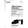
ADJUSTMENT
A MAIN C.B
5 6
4 3 5 7
SFR701
8
DOLBY GND
VT GND TC201 TC251 TC202 TP2 (LCH) TP3 (RCH) TP1(VT) IFT251 IC251
11 12
VR251
L251 BAR ANT
2
9
1
B
JACK C.B PHONES J402
8
<TUNER SECTION>
1. AM IF Adjustment IFT251 .................................................................. 450 kHz 2. FM IF Adjustment TC202 ................................................................ 10.7 MHz 3. AM VT Check Settings : � Test point : TP1 (VT) Method : Set to AM 531 kHz and check that the test point voltage is 1.3 ± 0.3V. Then set to AM 1602 kHz and check that the test point voltage is less than 6.7~ 8.2V. 4. FM VT Check Settings : � Test point : TP1 (VT) Method : Set to FM 87.5MHz and check that the test point voltage is 3.6 ± 0.4V. Then set to FM 108.0MHz and check that the test point voltage is less than 6.8~9.0V. 5. AM Tracking Adjustment L251 .................................................................... 630 kHz TC251 .................................................................1440 kHz 6. FM Tracking Adjustment TC201 ............................................................... 87.5 MHz
7. FM VCO Adjustment Settings : � Adjustment location : VR251 Method : Connect a frequency counter to pin 11 and 12 of IC251, adjust VR251 for VCO to 19kHz ± 100Hz.
<TAPE PLAYER SECTION>
8. Tape Speed Adjustment Settings : � Test tape : � Test point : TTA�100 PHONES JACK (J402) � Volume : MAX. � Adjustment location : SFR701 Method : Play back the test tape and adjust SFR701 for 3015Hz ± 10Hz(FWD) and 3015Hz ± 45Hz (REV).
9. Dolby Level Check Settings : � Test tape : TTA-200 � Test point : TP2(Lch), TP3(Rch) � Volume : MIN. � DOLBY SW : OFF Method : Connect an electrolytic capacitor (10uF/16V) to measured instrument and test point, check the voltage for 31.6mV ± 1dB.
23
|
|
|
> |
|