|
There are currently no product reviews.
 ;
Das ging ja sehr unkompliziert hat bestens geklappt und die Quallität ist auch noch gut.
Vielen Dank dafür.
;
Everything okay, thanks a lot. It was a pleasure for me to make a deal with you.
;
A deal without problems, very fast and the manual is a good quality. Sorry for the my english.
;
Superb service and excellent quality of the document received
;
no problems with the purchase of a circuit diagram
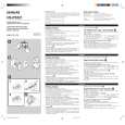
ADJUSTMENT
MECHANICAL EXPLODED VIEW 1 / 1
A MAIN C.B
VOLUME
VR 1
PHONES SFR 51 J1
1
12
2
1. Tape Speed Adjustment Settings : � Test tape : TTA�100 (Tape center) � Test point : PHONES JACK (J1) � Adjustment location : SFR51 Method : Play back the test tape and adjust SFR51 so that the frequency is 3000Hz±10Hz.
2. Head Azimuth Adjustment Settings : � Test tape : � Test point : � Ajustment location: Method: TTA�300 PHONES JACK (J1) Head azimuth adjustment screw
Play back the test tape and adjust the screw so that the output becomes maximum and same phase.
7
8
|