|
|
|
Categories
|
|
Information
|
|
Featured Product
|
|
|
 |
|
|
There are currently no product reviews.
 ;
The manual is excellent, well detailed, and divided into two parts. Received very quickly. Thank you.
;
a solid deal - quick and without any problems.
I life in europe - with downloads no loosing time
once again
 ;
got exactly what i ordered in a very timely manner. will use again for other manuals
;
I'm happy. Good quality. Very helped me with my work..............................
;
This is the second Manual I have ordered from owner-manuals, I give it five stars because it is exactly what I expected given the age of the equipment. So the contents look a bit aged and the pictures a bit grainy, it fulfills my needs and I am glad I can still get hold of them.
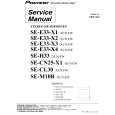
ADJUSTMENT
A MAIN C.B L451 (BAR-ANT)
VT GND PHONES
5 1 5
8 6
*
J101
CT401
CT402
2
GND TP2 (RCH)
IFT451
IC451 VT GND
11 12
CT451
SFR 201
8
9
TP1 (LCH)
7
VR101
VOLUME
SFR 451
TP3(VT)
B
A
C
D
9
Note :
9
34
* : J101 On the other side of the components.
<RADIO SECTION>
1. AM IF Adjustment IFT451 ................................................................... 450 kHz 2. FM IF Adjustment CT402 .................................................................. 10.7 MHz 3. AM VT Check Settings : � Test point : TP3 (VT) Method : Set to AM 531 kHz and check that the test point is 1.2 V ± 0.3 V. Then set to AM 1602 kHz and 1check that the test point is less than 7.8 V. 4. FM VT Check Settings : � Test point : TP3 (VT) Method : Set to FM 87.5 MHz and check that the test point voltage is 3.5 V ± 0.3 V. Then set to FM 108.0 MHz and check that the test point voltage is less than 8.5 V. 5. AM Tracking Adjustment L451 ...................................................................... 630 kHz CT451 .................................................................. 1440 kHz 6. FM Tracking Adjustment CT401 .................................................................. 87.5 MHz 7. FM VCO Adjustment Settings : � Adjustment location : SFR451 Method : Connect a frequency counter to pin 11 & 12 of IC451. Adjust SFR 451 such that the frequency counter indicates 19kHz ± 100 Hz.
<TAPE PLAYER SECTION>
8. Tape Speed Adjustment Settings : � Test tape : TTA�100 � Test point : Phones Jack (J101) � Adjustment location : SFR201 � DSL : OFF Method : Play back the test tape and adjust SFR201 for 3015 Hz ± 10 Hz (FWD) and 3015 Hz ± 50 Hz (REV). Then confirm WOW is less than 0.5%. 9. Dolby Level Adjustment Settings : � Test tape : TTA�200 � Test point : TP1(LCH), TP2(RCH) � Adjustment location : A, D (LCH) B, C (RCH) � VOLUME : MIN "0" � DOLBY SW(AU) : OFF Method : Connect a coupling capacitor (10 uF / 16 V) between the test point and AC voltage meter about. Check the test point voltage for 32 mV ± 1.0 dB. If TP1,TP2 level is different from the SPEC, perform this adjustment following the procedure below: Out level 32mV + 1dB up 32mV + 2dB up 32mV + 2.7dB up TP2 (RCH) 32mV + 1dB up 32mV + 2dB up 32mV + 2.7dB up Solder place D A A, D C B B, C
TP1 (LCH)
� 10� �6 �
|
|
|
> |
|