|
There are currently no product reviews.
 ;
I purchased this manual to repair my Teac set and with the support of this manual I rectified the problem.
Thanks Owner-Manuals.com
;
Excellent service manual, i didn't believe i could find it for such old product, it is very explanatory, managed to fix the disk player!!!
 ;
Nice manual. Clear copy and very rare, to boot. Great price, too!
;
Excellent service manual. Complete service info. with schematics, step-by-step instructions and illustrations. Well worth the price!
;
Great product, helped me to restore vintage walkman cassette.
Just some pictures could be little bit more sharp and contrast
Thank you
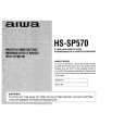
ADJUSTMENT
u MAIN
C.B
@@
@(
)(
}5 .�
(
]ITiiii@
R56 @@=+f�h �@=+J�h _ R5 o R54 @T Ll:
u
IC2
�+
[
L1OI
------@
LI 02 L4 BAR ANT
TC71
c)�
�
la L5
m
SFR1
n
ICI E
lt3.71vfHz
6
<RADIO SECTION> 1, AM IF Adjustment L5 .,,,,,,.,.,,,,,,,,, ,,,,,.,,,,.,,,,,,,, ,,,,.,,,,,,,,.,,,,,,,,,,,,,,,,.,,,.,,,,,,, 450kHz 2. FM IF Adjustment L2...............................................................................
dAPE PLAYER SECTION> 9. Taue sDeedadjustment Seitin&: q tape: �lTA- 100 (TAPE CENTER) T;st �Test point: PHONES JACK (J2) q Adjustment location : SFR1 Method: Play back the test tape and adjust for 3015 ~ 10 Hz. 10, GOVERNOR Adjustment Perform the STOP -) PLAY and REVERSE operations (or PAUSE ON+ OFF) after the motor is replaced. When the tape starts running smooth, this adjustment is not necessary. If wow is conspicuous at the beginning of the tape-run, perform this adjustment following the procedure below. 1) Solder only medium resistor pattern (C)of the MOTOR AND GOVERNOR MATCHING ADJ. resistor group. 2) Set the tape speed (using speed adjustment SFR). 3) Restrict the motor rotation by hand (or turn PAUSE ON). 4) Remove your hand and listen to the begining of the taperun. 5)When the rise of tape running is smooth, no more adjustment is necessary. If wow continues for 1 to 2 seconds at the rise time, change the combined resistance according to procedure 6 and check that the tape starts running smooth, 6) Solder the resistor pattern according to the table below. (yproe$re Solder Open Solder step(l) Step(2) Open Open Solder
3. FM VT Adjustment Settings: �Test point: TP 1 q Adjustment location: L 2 Method: Set to FM 76.O/59.75cYU>MHz, and adjust L2 so that the test point becomes 0.9V -1. lV. And set to FM 108.1MHz so that the test point is less than 8.6V, 4. AM VT CHECK Settings: q Test point : TP 1 Method: Set to AM 530kHz and check that the test point is 0.85V - 1.45V. Then set to AM 1710 kHz and check that the test point is less than 8.5V. 5. TV VT Adjustment<YU> Settings: q Test point: TP 1 q Adjustment location : L 101 Method: Set to TV lch(162.4MHz) and adjust L101 that the test point becomes 0,9V--1.1V.Then set to TV5ch(215.75MHz) so that the test point is less than 8,5V, 6. AM Tracking Adjustment L4 ............................................................................... 630kHz TC71 ............................................................................. 1440kHz 7. FM Tracking Adjustment LI ........................................................... 76.0MHzd3xcept YU> L1!,.,,,,..,.,,O ,.,,,,,,,,,.,,,,,,,,,,,,,,,,,,.,,,,,,,,,,,,,, 59.75MHZ<YU> ,0,,,,. Method: Set to 108.lMHz and make sure to obtain amplitude of 76,0/59,75<YU>MHz or more on tracking scope.
Pattern High resistance(A) Medhtm resistance(C) Low resistance(B)
Step(3) steP@) Open Solder
Solder Solder Solder Solder Solder
Solder Open
8. TV Tracking Adjustment cYU> Tune tolch and adjust L102 to get the MAX output. Tune to 5ch and make sure to obtain amplitude of 1ch or more on tracking scope. lch ........................................................................... 162,4MHz 5ch ......................................................................... 215.75MHz
7) Finally re-check the tape speed, Caution: Cool the patterns down to normal temperature afrer soldering. Ifthe pattern remains heated, the governor circuitoes not operatenormally. d
-17-
 $4.99 HSSP570 AIWA
Owner's Manual Complete owner's manual in digital format. The manual will be available for download as PDF file aft…
|