|
|
|
Categories
|
|
Information
|
|
Featured Product
|
|
|
 |
|
|
There are currently no product reviews.
 ;
The quality is quite good and clear. Nothing of the informations inside is lost during the digitalizing process
 ;
Very good service, fast downloads and good manuals.
;
Good qulity. Even as it is an old manual (from 1991-1992) it has a good scanned quality and is complete, including user's manual, disassembly intructions, diagrams and schematics, ajustments, troubleshooting and parts list, as usual with SONY manuals and Owner-manuals service.
;
tres bon document
cela a permis de verifier la connection de l'ecran
merci
salutations
;
The manual was of good quality with high resolution schematic diagrams.
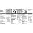
ADJUSTMENT
3) Restrict the motor rotation by hand (or turn PAUSE ON). 4) Remove your hand and listen to the begining of the
PRACTICAL
SERVICE
FIGURE
u
MAIN C.B
tape-run. 5) When the rise of tape running is smooth, no more adjustment is necessary. If wow continues for 1 to 2 seconds at the rise time, change the combined resistance according to procedure 6 and check that the tape starts running smooth. 6) Solder the resistor pattern according to the table below:
Pattern
High
(ya~$l Solder Open Solder
step (1) Step (2) Step (3) Open Solder Solder Open Open Solder Solder Solder Solder
dlJNER SECTION> Sensitivity : (IHF, THD 3%) FM Less than 19dB [at 98MHz] FM Less than 20dB [at 88/ 108MHz] (S/N 10dB) AM Less than 59dB [at 600kHz] Less than 55dB [at 1000 / 1400kHz] Intermediate frequency : FM 10.75MHz Y O.lMHz AM 455kHz * 3kHz FM stereo separation : More than 16dB [at 98.OMHZ] <TAPE SECTION> Tape speed: Wow & flutter: Take-up torque : F.F torque : Rew torque: Back tension : S/N ratio : Distortion : Noise level : Frequency response : Test tape:
Less than 0.52% (RMS) 25- 45g-cm (FWD, REV) More than 60g-cm 301 5Hz * 50Hz
resistance (B)
15 I
o
Medium resistance (A) Low resistance (C)
-f-o&
LI02 Pvcl 01
I
7) Finally re-check the tape speed. Caution : Cool the patterns down to normal temperature after soldering. If the pattern remains heated, the governor circuit does not operate normally.
More than 60g-cm 1- 4g-cm (FWD, REV) More than 43dB (PB, DC) Less than 3.0% (PB, DC) Less than 7.OmV (Vol MAX, PB, DC) 63Hz + l/-5dB - 8kHz * 4dB (NORMAL) TTA- 100 �M�A- 210 TTA� 300 lTA- 320(120p)/310 (70@
Q2a=lxD*
L101 BAR ANT
TRANSISTOR
~APE PLAYER SECTION>
c
.
ILLUSTRATION
<RADIO
SECTION>
1. AM IF Adjustment L105 .........................................................,,..,,,,,,,.. . 450kHz 2. AM Frequency range Adjustment L104 .............................,..,,,,.,..,,..............,.,.,,..$517 A 5kHz TC 104........................................................... 1775 * 10kHz
3. AM Tracking Adjustment
6. Tape Speed Adjustment Settings : Test tape: Test point:
q q q q q q q q q
TTA-1OO PHONES JACK (Jl)
B
h.
;O:�:,
Q
..
::
Adjustment location : SFR51 Super BASS : OFF Tape/radio : TAPE Tape select: Ear guard : Direction : Volume:
E
L101 .........................................................,,,,,,,.,,,,,, 600kHz TC101 ..........................................,,..,...,.,,,, ,,..,,.,.,. 1400kHz 4. FM Frequency range Adjustment L103 ........................................................... 87.0 t O.lMHz TC 103....................................................... 109,0 * O.lMHZ 5. FM Tracking Adjustment L102 .................................................................... 88.OMHZ TC 102 ................................................................. 108.OMHZ Method :
NORM OFF FWD NON-CLIP (MAX -lOdB DOWN) Play back the test tape and adjust for 3015 f 10Hz (FWD) and less than 45Hz (REV) with respect to forward speed.
2SC2712 RN1411
7. Motor Load Adjustment Perform the STOP �> PLAY and REVERSE operations (or PAUSE ON �> OFF) after the motor is replaced. When the tape starts running smooth, this adjustment is not necessary. If wow is conspicuous at the begining of the tape-run, perform this adjustment following the procedure below. 1) Solder both resistor pattern (B) and (C)of the MOTOR AND GOVERNOR MATCHING ADJ. resistor group. 2) Set the tape speed (using speed adjustment SFR5 1).
5
6
 $4.99 HSTA381 AIWA
Owner's Manual Complete owner's manual in digital format. The manual will be available for download as PDF file aft…
|
|
|
> |
|