|
|
|
Categories
|
|
Information
|
|
Featured Product
|
|
|
 |
|
|
There are currently no product reviews.
 ;
I needed the manual immediately and I got it immediately. I couldn't find this manual anywhere else on the net. The site was easy to traverse, and the price was very reasonable. I'll definitely be back for any future needs.
 ;
I received a good service manual, with good resolution. Improve the instructions for the purchase because they are not well understood.
For the rest, so good.
Thanks Angel.
;
Very good documentation for the Grundig 2077 model (as well as similar 800/900/1000 series radios). The first two pages are a summary of reception specifications and output capability. The third page is the tuner dial indicator and dial cord routing diagram. the final ~5 pages are the schematics for the various models (including 2077). The scan quality of the schematics are good, adn can be easily read if zoomed in. The documents are in German, not English as stated. It would have been nice to have the tuning sequence and settings, and some trouble shooting materials... or component and wiring map.
;
Perfect like it was descriped, Perfect like it was descriped
;
Very good detail, all pages clear, exactly what I needed
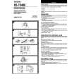
ADJUSTMENT
<TAPE PLAYER SECTION>
A MAIN C.B
6
8
8
6. Tape Speed Adjustment Settings : � Test tape :
TTA�100
SFR 1
D C B A
(TAPE CENTRE) � Test point : Phones Jack (J1) � Adjustment location : SFR1 � Tape/radio : TAPE � S-BASS : OFF � Volume : NON-CLIP Method :
VR1
* *
(MAX -10dB ) Play back the test tape and adjust SFR1 for 3000Hz ± 10Hz. Then confirm WOW is less than 0.50%.
42
VOLUME
L102
5 3
VC101
TP1(VT) * * L103
7. Azimuth Adjustment Settings : � Test tape : � Test point : � S-BASS : � Tape/radio : � Volume : � Adjustment location : Method :
PHONES
TTA�330/TTA�420 Phones Jack (J1) OFF TAPE MAX Head azimuth adjustment screw Play back the 8KHz signal of the test tape and adjust the screw so that the output becomes maximum.
L105
J1
4 3
L101 (BAR-ANT) P HEAD
1
6
7 FWD
NOTE : * : On the other componets side.
8. Maximum Output Power Adjustment Settings : � Test tape : TTA�210 � Volume : MAX � S-BASS : ON Method : For <YU, YL> : � Short the shorting point B and C only. For <YZ> : � Short the shorting point B and C . � If output is less than 1.2mW(0.14V), short the shorting point A and D . � If output is more than 3.9mW(0.25V), open the shorting point B and C and short the shorting point A and D .
<RADIO SECTION>
1. AM IF Adjustment L105 ....................................................................... 450kHz 2. AM VT Check Settings : � Test point : TP1 (VT) Method : Set to AM 530kHz and check that the test point is more than 0.8V. Then set to AM 1710kHz and check that the test point is less than 8.7V. 3. AM Tracking Adjustment L101 ....................................................................... 630kHz VC101 .................................................................. 1440kHz 4. FM VT Adjustment Settings : � Test point : TP1 (VT) � Adjustment location : L103 Method : Set to FM 76MHz and adjust L103 so that the test point becomes 1.0V ± 0.1V. Then set to FM 108.1MHz and check that the test point is less than 8.5V. 5. FM Tracking Adjustment L102 ..................................................................... 76.0MHz
31
IC101
32
 $4.99 HSTX406 AIWA
Owner's Manual Complete owner's manual in digital format. The manual will be available for download as PDF file aft…
|
|
|
> |
|