|
|
|
Categories
|
|
Information
|
|
Featured Product
|
|
|
 |
|
|
There are currently no product reviews.
 ;
This manual is complete and of high quality. I am very pleased with the purchase.
;
Another excellent buy! A fully readable PDF archive. Good prints!!
;
It is wonderful done!!! a great job in scanning the manual. Superior quality in all the electric scheme. Very understandable and net!!! Thank you!
 ;
muy buen manual por lo completo de este algunos esquemas estan muy divididos lo que hace algo dificil el seguimiento.
;
very good manual, with detail and clarity in esquematic diagrams and waveforms .
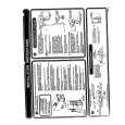
ADJUSTMENT
<TAPE PLAYER SECTION>
A MAIN C.B
6
8
8
6. Tape Speed Adjustment Settings : � Test tape :
TTA�100
SFR 1
D C B A
(TAPE CENTRE) � Test point : Phones Jack (J1) � Adjustment location : SFR1 � Tape/radio : TAPE � S-BASS : OFF � Volume : NON-CLIP Method :
VR1
* *
(MAX -10dB ) Play back the test tape and adjust SFR1 for 3000Hz ± 10Hz. Then confirm WOW is less than 0.50%.
42
VOLUME
L102
5 3
VC101
TP1(VT) * * L103
7. Azimuth Adjustment Settings : � Test tape : � Test point : � S-BASS : � Tape/radio : � Volume : � Adjustment location : Method :
PHONES
TTA�330/TTA�420 Phones Jack (J1) OFF TAPE MAX Head azimuth adjustment screw Play back the 8KHz signal of the test tape and adjust the screw so that the output becomes maximum.
L105
J1
4 3
L101 (BAR-ANT) P HEAD
1
6
7 FWD
NOTE : * : On the other componets side.
8. Maximum Output Power Adjustment Settings : � Test tape : TTA�210 � Volume : MAX � S-BASS : ON Method : For <YU, YL> : � Short the shorting point B and C only. For <YZ> : � Short the shorting point B and C . � If output is less than 1.2mW(0.14V), short the shorting point A and D . � If output is more than 3.9mW(0.25V), open the shorting point B and C and short the shorting point A and D .
<RADIO SECTION>
1. AM IF Adjustment L105 ....................................................................... 450kHz 2. AM VT Check Settings : � Test point : TP1 (VT) Method : Set to AM 530kHz and check that the test point is more than 0.8V. Then set to AM 1710kHz and check that the test point is less than 8.7V. 3. AM Tracking Adjustment L101 ....................................................................... 630kHz VC101 .................................................................. 1440kHz 4. FM VT Adjustment Settings : � Test point : TP1 (VT) � Adjustment location : L103 Method : Set to FM 76MHz and adjust L103 so that the test point becomes 1.0V ± 0.1V. Then set to FM 108.1MHz and check that the test point is less than 8.5V. 5. FM Tracking Adjustment L102 ..................................................................... 76.0MHz
31
IC101
32
|
|
|
> |
|