|
|
|
Categories
|
|
Information
|
|
Featured Product
|
|
|
 |
|
|
There are currently no product reviews.
 ;
Excellent manual, detailed, very useful! Exactly what I needed, I'd recommend it to all who need it. Although images are scanned easily readable and explicit. A valuable tool product at a price more than modest, take it with confidence and you will not regret it!
;
Clear and complete service manual. Easy now to restore my old Kenwood KD-1500.
Thanks a lot.
;
Thanks for this "hard to find" service manual. This Sony PS212A is a very good turntable that needed to be restored !
 ;
Excellent quality on these manuals. Same as having the original printed manual and incredibly useful when doing a custom install like me. Keep it up on the good work.
;
This is an excellent information source. Great quality and tons of info regarding technical service for the Technics SH8065.
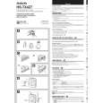
ADJUSTMENT
< TUNER SECTION > 1. AM IF Adjustment IFT201 .................................... 450kHz <TX426 / 429> IFT601 .................................... 450kHz <TX427> <TAPE PLAYER SECTION> 1. Tape Speed Adjustment Settings : � Test tape : TTA-100 (TAPE CENTER) � Test point : PHONES (J101) � Adjustment location : SFR101 � Super Bass : OFF � Volume : MAX Method : Play back the test tape and adjust SFR101 for 3000Hz ± 10Hz (FWD). Then confirm WOW is less than 0.50%.
2. AM Tracking Adjustment L201 ........................................ 630kHz <TX426 / 429> TC201 ..................................... 1440kHz <TX426 / 429> L601 ........................................ 630kHz <TX427> TC601 ..................................... 1440kHz <TX427> 3. FM IF Adjustment TC501 ..................................... 10.7MHz <TX427>
4. FM Tracking Adjustment L202 ........................................ 76MHz <TX426 / 429> L502 ........................................ 71.75MHz (TV 4ch) <TX427>
2. Azimuth Adjustment Settings : � Test tape : TTA-330 � Volume : MAX � Adjustment location : Head azimuth adjustment screw Method : Play back (FWD) the test tape and adjust screw so that the 8kHz signal output is maximum.
5. FM VT Adjustment Settings : � Test point : TP1 (VT) � Adjustment location : L203 <TX426 / 429> L504 <TX427> * Short IC501 Pin 6 (PA0) and Pin 7 (PB3) together. <TX426 / 429> * Connect cathode of diode to Pin 6 (PA0) and anode to Pin 7 (PB3) of IC801. <TX427> Method : Set to FM 76MHz <TX426 / 429>, FM 59MHz <TX427> and adjust L203 <TX426 / 429>, L504 <TX427> so that the test point becomes 1.1V ± 0.1V <TX426 / 429>, 1.4V ± 0.1V <TX427>. Then set to FM 108.1MHz and check that the test point is less than 7V <TX426 / 429>, less than 11V <TX427>.
6. TV Tracking Adjustment <TX427> L501 ........................................ 162.4MHz (WEATHER 2ch)
7. TV VT Adjustment <TX427> Settings : � Test point : TP1 (VT) � Adjustment location : L503 * Connect cathode of diode to Pin 6 (PA0) and anode to Pin 7 (PB3) of IC801. Method : Set to 162.4MHz (TV 1ch) and adjust L503 so that the test point becomes 2.0V ± 0.1V. Then set to 215.75MHz (TV 5ch) and check that the test point is less than 10V.
� 19 �
 $4.99 HSTX427 AIWA
Owner's Manual Complete owner's manual in digital format. The manual will be available for download as PDF file aft…
|
|
|
> |
|