|
|
|
Categories
|
|
Information
|
|
Featured Product
|
|
|
 |
|
|
There are currently no product reviews.
 ;
Wellll again thank you very much fast and effective. Clear and well done for such an old TV!!!!
;
It has all the information you will need to fix it. The main circuit diagram is only A4 but being a PDF, you can print it to any size - I did it on two sheets of A3 and it didnt lose any detail - just made it readable when pinned up above the bench. I've found the fault, just need to buy some obscure bits to get it going again!
I cant fault the process, I paid for the manual in the morning and it was ready to download by lunch time.
 ;
Very good copy in a 54 pages PDF archive. This is my sixth purchase here. :)
;
Another excellent buy! File too clear and explanatory.
;
A manual hard to find. It was very helpful to restore my device.
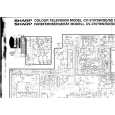
CHASSIS (MOLD B) SECTION, STOCKER SECTION AND SLIDER (SELECTION)
Note: In mounting the parts, refer to page 11 and 12.
6 two screws (PTPWH M2.6) 5 stocker section
7 slider (selection) 8 washer
9 compression spring
pulley (LD)
1 three screws (BVTP M2.6)
4 two step screws
2 chassis (mold B) section Note: Rotating the pulley (LD), shift the slider (selection) to the left.
4 two step screws
3 gear (eject)
GEARS INSTALLATION
3 gear (gear B)
portion A
Adjust the gear (gear B) with the portion A as shown.
1 Slide the slider (U/D) fully in the arrow direction.
4 gear (gear A) 2 gear (U/D slider) slider (U/D) gear
gear (gear B)
linearly
Adjust the gear so that it meshes with the bottom tooth of slider (U/D)gear, as shown.
Adjust so as to be aligned with gear (B) linearly,as shown.
10
|
|
|
> |
|