|
|
|
Categories
|
|
Information
|
|
Featured Product
|
|
|
 |
|
|
There are currently no product reviews.
 ;
The service was quick and simple, finding the service manual easy and it appears to be the original with colour schematics. It contained the info I was after and so sorted the problem.
I have copied it to CD and attached the envelope to the inside back cover of the owners manual. Good manual and excelent service. Robin Wood, Wood Electronics, New Zealand.
;
Exactly what was needed to assess the product - excellent value and great service
 ;
Nice to have the service manual for the Sony DCR-TRV345E now. The document is of excellent quality.
;
MACKIE HR824 26 pages English-only Service Manual contains:
1) HR824 technical overview with the description of front and rear panel switches.
2) HR824 specs
3) Block Diagram
4) Wiring Diagram
5) Packaging management
6) Spare part & final assembly list (for PCB rev A and B) + exploded view
7) Test Procedures (where, how to measure voltage...) including Test Point diagram on the PCB.
8) IC and Transistor charts.
Excellent guide: very clear, good scan quality enabling us to print readable diagram :-)
Note:
Mackie HR824 make extensive use of surface mount devices (SMD). Service on the HR824 must
only be undertaken by experienced service technicians with the right tools, experience and patience to perform surface mount rework when needed.
;
This Service manual is very well scanned and its clean to read, no any anti-theft words that un-english could understand. I got my CCD600 working with this manual and it´s clear shematics :)
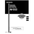
ELECTRICAL ADJUSTMENT
TUNER C.B
FFE801
3
6
IC BLOCK DIAGRAM IC, BU4094BCF
TP6
4
L772 TP1 L981
L771
TP3 TP2 1/3 TP4
IC771 TP5
4
< TUNER SECTION >
1. Clock Frequency Check Settings: � Test point: TP2 (CLK IC771 pin30) Method: Set to AM 1710kHz and check that the test point becomes 2160kHz±45Hz. 2. AM VT Check Settings: � Test point: TP1 (VT) Method: Set to AM 1710kHz and check that the test point is less than 8.5V. Then set to AM 530kHz and check that the test point is more than 0.6V. 3. AM IF Adjustment Settings: � Test point: TP5, TP6 L772 .............................................. 450kHz 4. AM Tracking Adjustment Settings: � Test point: TP5, TP6 � Adjustment location: L981 (1/3) Method: Set to AM 999kHz and adjust L981 so that the test point becomes maximum. 5. FM VT Check Settings: � Test point: TP1 (VT) Method: Set to FM 87.5MHz, 108.0MHz and check that the test point is more than 0.5V (87.5MHz) and less than 8.0V (108.0MHz). 6. DC Balance/Mono Distortion Adjustment Settings: � Test point: TP3, TP4 � Adjustment location: L771 � Input level: 60dB Method: Set to FM 98.0MHz and adjust L771 so that the voltage between TP3 and TP4 becomes 0V±0.04V. Next, check that the distortion is less than 1.3%.
IC, M62431FP
PRACTICAL SERVICE FIGURE
< TUNER SECTION >
<FM SECTION> Signal to noise ratio: Distortion: (Input: 60dB) Stereo separation: Intermediate frequency: <AM SECTION> Sensitivity: (S/N 20dB) Signal to noise ratio: (Input: 74dB) Distortion: Intermediate frequency: More than 62dB (at 98.0MHz) Less than 2.0% (at 98.0MHz) More than 22dB (at 98.0MHz) 10.7MHz
Less than 60dB (at 600kHz) Less than 58dB (at 1000/1400kHz) More than 36dB (at 1000kHz) Less than 1.5% (at 1000kHz) 450kHz
IC, M62439SP
35
36
 $4.99 HTD390 AIWA
Owner's Manual Complete owner's manual in digital format. The manual will be available for download as PDF file aft…
|
|
|
> |
|