|
There are currently no product reviews.
 ;
Perfect like it was descriped, Perfect like it was descriped
;
Very good detail, all pages clear, exactly what I needed
;
Excellent service, and just what I needed to service my TU-7700. All pages of the manual are clear and easily readable.
;
Excellent printing quality.
A complete and very usefull service manual with all details.
GREAT SERVICE AT VERY LOW PRICE!
A+++++++++++++++++++++++++
;
We received the manual in a timely manner and it was exactly what we were expecting. Excellent replacement for original Service Manual.
All schematics are very legible. We are really satisfied.
There are 7812, 7805 and LM317 linear regulator ICs on the power supply to generate +5V, -5V, +12V, -12V and +3.3V for the device. On the standby mode just +12Vst and +5V supplies are generating for standby power consumption. The ES6008/18 requires 2.5V to operate. This voltage is generated from +5V.
13 CONNECTORS
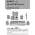
13.1 ATAPI DRIVE STANDARD CONNECTOR
The I/O connector is a 40-pin connector as shown in figure A.1, with pin assignments as shown in table A.1. The connector shall be keyed to prevent the possibility of installing it upside down. A key is provided by the removal of pin 20. The corresponding pin on the cable connector shall be plugged. The cable plug, not the receptacle, governs the pin locations. The way in which the receptacle is mounted on the printed circuit board affects the pin positions, and pin 1 shall remain in the same relative position. This means the pin numbers of the receptacle may not reflect the conductor number of the plug. The header receptacle is not polarized, and all the signals are relative to pin 20, which is keyed. By using the plug positions as primary, a straight cable can connect devices. As shown in figure A.1, conductor 1 on pin 1 of the plug shall be in the same relative position no matter what the receptacle numbering looks like. If receptacle numbering was followed, the cable would have to twist 180 degrees between a device with top-mounted receptacles, and a device with bottom-mounted receptacles.
40
20 Circuit board
1 2 Circuit board 40 Figure A.1 - 40-pin connector mounting 20 1 2
16
|