|
|
|
Categories
|
|
Information
|
|
Featured Product
|
|
|
 |
|
|
There are currently no product reviews.
 ;
Exactly what was needed to assess the product - excellent value and great service
;
A site where discontinualed schematic diagrams and back dated information can be found on discontinued radios tv's and any electronic equipment can be found. Newer manuals either Service and operating manuals. Radio amateurs should find this site a great source for ham radio equipment manuals. I will return to this site should I need information on any electrical equipment. priced easy to download in a PDF format and print pages need to undertake the repair.
;
Quality scan of the original. All the detail necessary to troubleshoot, repair and adjust the unit. I'm sure I will be downloading more manuals in the future as the need arises.
;
Exactly as described, a Service Manual complete with the schematics and PCB layout delivered in a timely manner. Many thanks for the great service.
 ;
some of the writing is a bit blur but the part in the schmatic was great and i have fixed the machine thanks
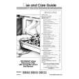
HTP-940 ADJUSTMENT PROCEDURE
SKW-940 : POWERED SUBWOOFER / ADJUSTMENT OF IDLING CURRENT
[When] 1. Exchange transistors (Q505 - Q519). 2. Exchange MAIN PC board ass'y (NAAF-8829). [Procedure] <Note> No speaker load and No input signal. 1. Short test point P631 for amplifier is under active mode. 2. Adjust the trimming resistor R544 so that the reading of multimeter becomes 52 ohm to 53 ohm. 3. Connect the DC voltmeter to test point P531. <Fig-1> 4. Connect the AC power cord into a wall outlet. 5. Press POWER button to turn on the unit. (MPP type only) 6. Confirm the voltage of above point after 6 minutes to 8 minutes. (Heat running) 7. When less than 3.20 mV : Readjust the trimming resistor above so that the voltage becomes 4.5 mV to 5.0 mV. When 3.30 mV to 5.20 mV : Not necessary to adjust. When 5.21 mV to 10.0 mV : Readjust the trimming resistor above so that the voltage becomes 5.0 mV to 5.5 mV. When 10.1 mV to 20.0 mV : Readjust the trimming resistor above so that the voltage becomes 5.6 mV to 6.0 mV. 8. Press POWER button to turn off the unit. (MPP type only) 9. Disconnect the DC voltmeter. 10. Disconnect the AC power cord from a wall outlet.
100 ohm (1/4W) DC voltmeter
<Fig-1>
Test point
Trimming resistor
Test point
R544
P531
P531
MAIN PC board ass'y "NAAF-8829"
Test point
P631
Short
|
|
|
> |
|