|
|
|
Categories
|
|
Information
|
|
Featured Product
|
|
|
 |
|
|
There are currently no product reviews.
 ;
Very good reproduction (copy) of original manual. Didn't have a parts list, but schematic was completely labeled with parts. Complete instructions on how to adjust mechanical functions of the 8-track deck. Well worth having and at a very reasonable cost.
;
It's a full manual. All the parts are in there. I haven't found the problem yett, but I am working on it; hope I can rebuild the part myself. To make it more secure and unbreakable this time. Because the part has failed several times before and costs a lot to let it be repaired.
Thanks so much for this rich illustrated and parted manual.
;
I downloaded the document. The manual was complete, well scanned and everything was legible. I could zoom in see what I needed to know. There's not much more that you can ask.
;
It was complete service manual with all needed service informations. Thanks.
 ;
El manual esta muy detallado, los numeros de partes y los esquemas de despiece son correctísimos y muy claros, tanto para los técnicos experimentados como para los novatos.
HTV-A1
Diagnosis Method for the AFPS Assy
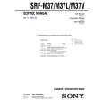
(1) Remove the three screws A fixing the Heat sink. (2) Remove the three PCB Holders and then remove the Heat sink. (Refer to Fig.1) (3) Remove the screw B, remove the two screws C, remove the two push rivets D, and then remove the AFPS assy. (Refer to Fig. 3) (4) Short-circuit KN101 of the AFPS assy and KN1001 of the JACK assy. (5) Short-circuit all test terminals of the AFPS assy (SPRY, ACRY, PWON) to GNDD. (6) Remove C6031, enter an audio signal to the AL4 (Lch in) terminal, and analyze the AFPS assy. (Refer to Fig. 4)
Push Rivet D Screw C
JACK Assy
Screw B
Push Rivet D
AFPS Assy
Fig. 3
KN1001 Short-circuit SPRY, ACRY and PWON terminals to GNDD. Remove C6031 JACK Assy
Enter an audio signal
A
AFPS ASSY
SIDE A
Fig. 4
AFPS Assy
KN101
25
|
|
|
> |
|