|
|
|
Categories
|
|
Information
|
|
Featured Product
|
|
|
 |
|
|
There are currently no product reviews.
 ;
The Service Manual for the Kenwood KR-V55R provided by owner-manuals.com was as described/advertised. The contents provided the necessary information to effect a diagnosis of the unit. The schematics above all else was instrumental in tracing the the signal flow from component to component.
 ;
This manual was the factory original. Excellent value and contained all the details I needed. Easy dowwnload provided the information when I needed it.
;
Impeccable, document très complet. Perfect, i get all i need. All schematic are correct. Thanks
;
The manual is of better quality compared to other. I found it less expensive and therefore it it is the best buy cost vs quality.
;
I bought the service-manual of the sony ICB-1020(an old transmitter-receiver) at "www.Owners-Manual.com", I found the service-manual for a fairly cheap price(in comparison with other sellers). I filled in some questions, payed the order with Ideal, and within 24 hours I had my service manual. I was very happy:In no time I had my service-manual and everything, but literally everything was noted down in the manual; the electronic scheme, the parts list, etcetera.
A very practical, reference-document.
HV- 29LPZ
SPECIFIC SERVICE INSTRUCTIONS
DISASSEMBLY PROCEDURE
REMOVING THE REAR COVER
1. Unplug the power c ord. 2. Remove the 16 screws marked ! as shown in the Fig. 1. 3. Withdraw the rear cover toward you.
CHECKING THE PW BOARD
To check the back side of the PW Board. 1) Pull out the chassis . (Refer to REMOVING THE CHASSIS). 2) Erect the c hassis vertically so that you c an easily check the back side of the PW Board. [CAUTION] " When erec ting the chassis, be careful s o that there will be no contacting with other PW Board. " Before turning on power, make sure that the wire connector is properly connec ted. " When conducting a check with power supplied, be sure to c onfirm that the CRT EARTH WIRE (BRAIDED ASS�Y) is connected to the CRT SOCKET PW board.
REMOVING THE AV TERMINAL BOARD
" After removing the rear cover. 1. Remove the 5 screws marked " as shown in the Fig. 1. 2. Withdraw the AV terminal board toward you.
REMOVING THE CHASSIS
" After removing the rear cover. 1. Slightly raise the both sides of the c hassis by hand and remove the 2 claws under the both s ides of the chas sis from the front cabinet. 2. Withdraw the chass is backward. (If necess ary, take off the wire clamp, connectors etc.)
WIRE CLAMPING AND CABLE TYING
1. Be sure to clamp the wire. 2. Never remove the c able tie used for tying the wires together. Should it be inadvertently removed, be sure to tie the wires with a new c able tie.
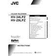
REMOVING THE DOME SPEAKER BOX / SPEAKER
" After removing the rear cover. 1. As s hown in Fig. 1, remove the remove the dome speaker box. 2. Remove the 5 screws marked $ remove the dome box. 3. Remove the 4 screws marked % remove the HONE RING. 4. Remove the 4 screws marked & remove the speaker. 2 screws marked # , then as shown in the Fig.2, then as shown in the Fig.2, then
DOME SPEAKER BOX
SPEAKER (Tweeter)
HORN
F (�4)
as shown in the Fig.2, then
E
(�4)
5. Follow the same steps when removing the other hand dome speaker box / speaker. NOTE : When removing the screws marked # of the dome speaker box, remove the lower side sc rew first, and then remove the upper one.
G
( �7) SPEAKER HORN PANEL HORN RING DOME BOX
REMOVING THE TWEETER SPEAKER
" After removing the rear cover. 1. Remove the 7 screws marked ' as shown in the Fig.2, then remove the HONE PANEL. 2. Then remove the tweeter speaker screws to remove it.
D
(�5)
Fig. 2
8
No.52012
|
|
|
> |
|