|
|
|
Categories
|
|
Information
|
|
Featured Product
|
|
|
 |
|
|
There are currently no product reviews.
 ;
One address for rare manuals.Very good copy. Thank you.
Your
Klaus Husse
;
All ok. I pay 5 $ and now i have 92 pages of good scaned service manual for my oooooold akai. Now i will try to repair it.
;
good and ok, very nice , good and ok, very nice, good and ok, very nice
;
Super manual it contains all the things you need to service your Marantz 2100.
;
A very easy to understand and use manual. Well worth the money.
SECTION 3 DISASSEMBLY
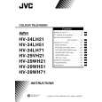
3.1 DISASSEMBLY PROCEDURE 3.1.1 REMOVING THE REAR COVER (1) Unplug the power cord. (2) Remove the 18 screws [A] as shown in the Fig. 1. (3) Withdraw the REAR COVER toward you. 3.1.2 REMOVING THE AV TERMINAL BOARD � Remove the REAR COVER. (1) Remove the 5 screws [B] as shown in the Fig. 1. (2) Withdraw the AV TERMINAL BOARD toward you. 3.1.3 REMOVING THE CHASSIS � Remove the REAR COVER. (1) Slightly raise the both sides of the CHASSIS by hand and remove the 2 claws under the both sides of the CHASSIS from the front cabinet. (2) Withdraw the CHASSIS backward. (If necessary, take off the wire clamp, connectors etc.) 3.1.4 REMOVING THE SPEAKER � Remove the REAR COVER. (1) Remove the 2 screws [C], and remove the SP HOLDER as shown in Fig. 1. NOTE : When removing the screws [C] of the SP HOLDER, remove the lower side screw first, and then remove the upper one. (2) Remove the 4screws [D] attaching the SPEAKER. (3) Follow the same steps when removing the other SPEAKER. 3.1.5 CHECKING THE PW BOARD � To check the back side of the PW Board. (1) Pull out the CHASSIS. (Refer to REMOVING THE CHASSIS). (2) Erect the CHASSIS vertically so that you can easily check the back side of the PW Board. 3.1.6 CAUTION � When erecting the CHASSIS, be careful so that there will be no contacting with other PW Board. � Before turning on power, make sure that the wire connector is properly connected. � When conducting a check with power supplied, be sure to confirm that the CRT EARTH WIRE (BRAIDED ASS'Y) is connected to the CRT SOCKET PW board. 3.1.7 WIRE CLAMPING AND CABLE TYING (1) Be sure to clamp the wire. (2) Never remove the cable tie used for tying the wires together. Should it be inadvertently removed, be sue to tie the wires with a new cable tie.
(No.52200)1-7
|
|
|
> |
|